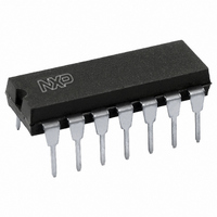
HEF4047BP,652 NXP Semiconductors, HEF4047BP,652 Datasheet - Page 12

HEF4047BP,652
Manufacturer Part Number
HEF4047BP,652
Description
IC MONO/ASTBL MULTVIBRTR 14-DIP
Manufacturer
NXP Semiconductors
Series
4000Br
Specifications of HEF4047BP,652
Logic Type
Astable, Monostable
Package / Case
14-DIP (0.300", 7.62mm)
Independent Circuits
1
Schmitt Trigger Input
No
Propagation Delay
50ns
Voltage - Supply
4.5 V ~ 15.5 V
Operating Temperature
-40°C ~ 85°C
Mounting Type
Through Hole
Elements Per Chip
1
Logic Family
HEF4000
Input Bias Current (max)
0.08 mA
Propagation Delay Time
320 ns, 130 ns, 100 ns
High Level Output Current
- 3.6 mA
Low Level Output Current
3.6 mA
Supply Voltage (max)
15 V
Supply Voltage (min)
3 V
Maximum Power Dissipation
750 mW
Maximum Operating Temperature
+ 85 C
Minimum Operating Temperature
- 40 C
Mounting Style
Through Hole
Operating Supply Voltage
3.3 V, 5 V, 9 V, 12 V
Lead Free Status / RoHS Status
Lead free / RoHS Compliant
Current - Output High, Low
-
Lead Free Status / Rohs Status
Lead free / RoHS Compliant
Other names
568-3106-5
933324240652
HEF4047BPN
933324240652
HEF4047BPN
Philips Semiconductors
Product specification
HEF4047B
Monostable/astable multivibrator
MSI
3. Retrigger mode operation
The HEF4047B can be used in the retrigger mode to extend the output pulse duration, or to compare the frequency of
an input signal with that of the internal oscillator. In the retrigger mode the input pulse is applied to pins 8 and 12, and
the output is taken from pin 10 or 11. Normal monostable action is obtained when one retrigger pulse is applied (Fig.8).
Extended pulse duration is obtained when more than one pulse is applied. For two input pulses, t
= t
’ + t
+ 2t
.
RE
1
1
2
For more than two pulses, t
(output O), terminates at some variable time, t
, after the termination of the last retrigger
RE
D
pulse; t
is variable because t
(output O) terminates after the second positive edge of the oscillator output appears at
D
RE
flip-flop 4.
Fig.8 Retrigger mode waveforms.
4. External counter option
Time t
can be extended by any amount with the use of external counting circuitry. Advantages include digitally
M
controlled pulse duration, small timing capacitors for long time periods, and extremely fast recovery time. A typical
implementation is shown in Fig.9.
The pulse duration at the output is:
t
=
N 1
–
t
+
t
+
1 2 t
ext
A
M
A
Where t
= pulse duration of the circuitry, and N is the number of counts used.
ext
Fig.9 Implementation of external counter option.
January 1995
12


