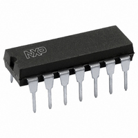
HEF4047BP,652 NXP Semiconductors, HEF4047BP,652 Datasheet - Page 3

HEF4047BP,652
Manufacturer Part Number
HEF4047BP,652
Description
IC MONO/ASTBL MULTVIBRTR 14-DIP
Manufacturer
NXP Semiconductors
Series
4000Br
Specifications of HEF4047BP,652
Logic Type
Astable, Monostable
Package / Case
14-DIP (0.300", 7.62mm)
Independent Circuits
1
Schmitt Trigger Input
No
Propagation Delay
50ns
Voltage - Supply
4.5 V ~ 15.5 V
Operating Temperature
-40°C ~ 85°C
Mounting Type
Through Hole
Elements Per Chip
1
Logic Family
HEF4000
Input Bias Current (max)
0.08 mA
Propagation Delay Time
320 ns, 130 ns, 100 ns
High Level Output Current
- 3.6 mA
Low Level Output Current
3.6 mA
Supply Voltage (max)
15 V
Supply Voltage (min)
3 V
Maximum Power Dissipation
750 mW
Maximum Operating Temperature
+ 85 C
Minimum Operating Temperature
- 40 C
Mounting Style
Through Hole
Operating Supply Voltage
3.3 V, 5 V, 9 V, 12 V
Lead Free Status / RoHS Status
Lead free / RoHS Compliant
Current - Output High, Low
-
Lead Free Status / Rohs Status
Lead free / RoHS Compliant
Other names
568-3106-5
933324240652
HEF4047BPN
933324240652
HEF4047BPN
Philips Semiconductors
Astable operation is enabled by a HIGH level on the
ASTABLE input. The period of the square wave at O and
O outputs is a function of the external components
employed. ‘True’ input pulses on the ASTABLE or
‘complement’ pulses on the ASTABLE input, allow the
circuit to be used as a gatable multivibrator. The
OSCILLATOR OUTPUT period will be half of the O output
in the astable mode. However, a 50% duty factor is not
guaranteed at this output.
In the monostable mode, positive edge-triggering is
accomplished by applying a leading-edge pulse to the
+ TRIGGER input and a LOW level to the
input. For negative edge-triggering, a trailing-edge pulse is
applied to the
+ TRIGGER. Input pulses may be of any duration relative
to the output pulse. The multivibrator can be retriggered
(on the leading-edge only) by applying a common pulse to
both the RETRIGGER and + TRIGGER inputs. In this
mode the output pulse remains HIGH as long as the input
pulse period is shorter than the period determined by the
RC components.
January 1995
Monostable/astable multivibrator
TRIGGER and a HIGH level to the
Fig.2 Pinning diagram.
TRIGGER
3
An external count down option can be implemented by
coupling O to an external ‘N’ counter and resetting the
counter with the trigger pulse. The counter output pulse is
fed back to the ASTABLE input and has a duration equal
to N times the period of the multivibrator. A HIGH level on
the MR input assures no output pulse during an ON-power
condition. This input can also be activated to terminate the
output pulse at any time. In the monostable mode, a HIGH
level or power-ON reset pulse must be applied to MR,
whenever V
HEF4047BP(N):
HEF4047BD(F):
HEF4047BT(D):
( ): Package Designator North America
DD
is applied.
14-lead DIL; plastic
14-lead DIL; ceramic (cerdip)
14-lead SO; plastic
(SOT27-1)
(SOT73)
(SOT108-1)
Product specification
HEF4047B
MSI


