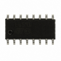
L6591 STMicroelectronics, L6591 Datasheet - Page 22

L6591
Manufacturer Part Number
L6591
Description
IC CTRLR PWM PROG CM HV 16SOIC
Manufacturer
STMicroelectronics
Specifications of L6591
Output Isolation
Isolated
Frequency Range
168 ~ 192kHz
Voltage - Input
8.7 ~ 22 V
Power (watts)
750mW
Operating Temperature
-40°C ~ 150°C
Package / Case
16-SOIC (0.154", 3.90mm Width)
Output Voltage
5 V
Input Voltage
25 V
Operating Temperature Range
- 40 C to + 150 C
Mounting Style
SMD/SMT
Duty Cycle (max)
50 %
For Use With
497-8335 - BOARD EVAL FOR L6591
Lead Free Status / RoHS Status
Lead free / RoHS Compliant
Other names
497-8286
Available stocks
Company
Part Number
Manufacturer
Quantity
Price
Part Number:
L6591
Manufacturer:
ST
Quantity:
20 000
Part Number:
L6591TR
Manufacturer:
ST
Quantity:
20 000
Application information
6.1
22/41
High-voltage start-up generator
Figure 40
generator). It is made up of a high-voltage N-channel FET, whose gate is biased by a 15
MW resistor, with a temperature-compensated current generator connected to its source.
With reference to the timing diagram of
converter the voltage on the bulk capacitor (Vin) builds up and, as it reaches about 80 V, the
HV generator is enabled to operate (HV_EN is pulled high) and draws about 1 mA. This
current, diminished by the IC consumption, charges the bypass capacitor connected
between pin Vcc (9) and ground and makes its voltage rise almost linearly.
As the Vcc voltage reaches the start-up threshold (13.5 V typ.) the IC starts operating and
the HV generator is cut off by the Vcc_OK signal asserted high. The IC is powered by the
energy stored in the Vcc capacitor until the self-supply circuit develops a voltage high
enough to sustain the operation. The residual consumption of this circuit is just the one on
the 15 MW resistor (
conditions, as compared to a standard start-up circuit made with an external dropping
resistor.
Figure 40. High-voltage start-up generator: internal schematic
shows the internal schematic of the high-voltage start-up generator (HV
≈
10 mW at 400 Vdc), typically 50-70 times lower, under the same
L6591
Vcc_OK
Doc ID 14821 Rev 5
15 M &
Figure
Ω
CONT ROL
HV_EN
41, when power is first applied to the
1 1
GN D
16
H VST ART
I
charge
I
HV
9
Vcc
L6591


