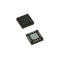
LDS8141-002-T2 IXYS, LDS8141-002-T2 Datasheet - Page 12

LDS8141-002-T2
Manufacturer Part Number
LDS8141-002-T2
Description
IC LED DRIVER WHIT BCKLGT 16WQFN
Manufacturer
IXYS
Series
LED-Sense™, Power-Lite™r
Type
Backlight, White LED (I²C Interface)r
Datasheet
1.LDS8141-002-T2.pdf
(22 pages)
Specifications of LDS8141-002-T2
Topology
High Side, Linear (LDO), PWM
Number Of Outputs
4
Internal Driver
Yes
Type - Primary
Backlight
Type - Secondary
White LED
Frequency
1.2MHz
Voltage - Supply
2.5 V ~ 5.5 V
Mounting Type
Surface Mount
Package / Case
16-WQFN, 16-miniQFN
Operating Temperature
-40°C ~ 85°C
Current - Output / Channel
32mA
Internal Switch(s)
Yes
Efficiency
80%
Lead Free Status / RoHS Status
Lead free / RoHS Compliant
Voltage - Output
-
Lead Free Status / Rohs Status
Details
Other names
LDS8141-002-T2-2
LDS8161/41
the default soft-start ramp mode, or s less than 10 ms
with the soft-start ramp mode disabled by setting bit 1
of the Configuration Register (1Eh) HIGH.
The calibration parameters for the temperature de-
rating and all customer-set parameters remain intact
until the part is reset or powered-down. Additionally,
the user can re-calibrate LDS8161/41 during times
when LED currents are brought to zero and thermally
stabilized by programming the calibration command
bit as discussed.
Factory preset values (upon completion of the power-
up initialization) are as follow (see Table 3):
Table 10: Recommended Register Load Sequence for LDS8161/41
© 2009 IXYS Corp.
Characteristics subject to change without notice
Sequence #
Reg Load
a) All LEDs are disabled and I
b) WLED mode (i.e. 1 De-rating LUT) selected
c) PWM dimming control is enabled Logarithmic
d) LED-Sense
10
11
12
13
14
15
1
2
3
4
5
6
7
8
9
and 1 PWM generator drives all 3 banks
(8160) or 2 banks (8141).
Mode with reset duty cycle = 0%.
disabled with the LUT in Logarithmic Mode
for a Nichia NSSW020BT WLED;
(Using the Factory Default De-Rating LUT)
(hex)
Reg
1Eh
4Ah
4Bh
A0h
A2h
C0h
D4h
D6h
49h
1Fh
00h
01h
02h
03h
05h
TM
temperature
User Loads Ex: FEh = 91% DC
User Loads Ex: F0h = 30mA
User Loads Ex: F0h = 30mA
Uer Loads Ex: F0h = 30mA
User Loads Per LED Used
User Loads Per LED Used
User Loads Ex: 3Fh = all
LEDA, B, C
Value (hex)
channels
CCh
de-rating
00h
18h
20h
36h
40h
04h
10h
= 0;
is
12
Comments
Initialize Configuration Register
Ta-Tj 0ffset = -20ºC
Set LED Shutdown Temp = 85ºC (Ta referenced)
Set 2x de-rate mode starting at 55C
Load Si Diode K factor for - 1.71mV/C
User loads LED K factor @ 1mA I
29h = -1.3mV/C for Nichia NSSW020BT
Load Si Diode ηfactor = 1.0
Load Si Diode Rs = 68 ohms
User loads LED Rs
61h = 17 ohms for Nichia NSSW020BT
User issues temp calibration command
User sets Current for Bank A.
User sets Current for Bank A.
User sets Current for Bank B.
User enabled LED channels
User sets PWM duty cycle for all channels
If the factory default loaded de-rating curve is used
as shown in Figure 7,
identifies the necessary registers and initialization
required after the power-up or reset state to operate
the LDS8161/41.
Figure 3: LDS8161/41 Default De-rate Curve
e) Soft start-up PWM ramp feature enabled;
Doc. No. 8141/61_DS, Rev. N1.0
then following Table 10
F


