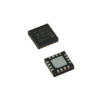
LDS8141-002-T2 IXYS, LDS8141-002-T2 Datasheet - Page 16

LDS8141-002-T2
Manufacturer Part Number
LDS8141-002-T2
Description
IC LED DRIVER WHIT BCKLGT 16WQFN
Manufacturer
IXYS
Series
LED-Sense™, Power-Lite™r
Type
Backlight, White LED (I²C Interface)r
Datasheet
1.LDS8141-002-T2.pdf
(22 pages)
Specifications of LDS8141-002-T2
Topology
High Side, Linear (LDO), PWM
Number Of Outputs
4
Internal Driver
Yes
Type - Primary
Backlight
Type - Secondary
White LED
Frequency
1.2MHz
Voltage - Supply
2.5 V ~ 5.5 V
Mounting Type
Surface Mount
Package / Case
16-WQFN, 16-miniQFN
Operating Temperature
-40°C ~ 85°C
Current - Output / Channel
32mA
Internal Switch(s)
Yes
Efficiency
80%
Lead Free Status / RoHS Status
Lead free / RoHS Compliant
Voltage - Output
-
Lead Free Status / Rohs Status
Details
Other names
LDS8141-002-T2-2
LDS8161/41
STANDBY MODES
The LDS8161/41 has a “soft” standby or sleep mode,
which the customer may set by I
addressing register 1Fh with bit 6 = 1 (see Table 4).
In the Standby Mode, the I
and all registers retain their programmed information.
In Standby Mode the LED drivers and internal clock
are powered off; however, internal regulators and
reference circuits remain active to insure power to the
digital sections to hold register values and maintain
I
current ~ 125 µA typical. For this mode, the EN pin
should be logic HIGH with signal level from 1.3 to V
voltage.
SHUTDOWN MODE
To set LDS8161/41 into the shutdown mode, the EN
pin should be logic low more than 10 ms. The
LDS8161/41 shutdown current is less than 1 µA.
© 2009 IXYS Corp.
Characteristics subject to change without notice
2
C interface communications. This results in standby
2
C interface remains active
2
C interface
IN
16
The LDS8161/41 wakes up from shutdown mode with
factory-preset default data. To preserve customer-
programmed data, use Normal standby mode.
PROGRAMMING MODES
The LDS8161/41 is factory preprogrammed with a
default temperature de-rating LUT that works with the
Nichia NSSW020BT WLEDs or equivalent. However,
specific LEDs and other user system conditions may
require user
compensation
parameters.
After initialization and user programming the user
should
command by writing Bit 4 = 1 in the Control register
1Fh. This conducts a real time calibration of the initial
starting temperature and actual LED parameters.
Upon completion, Bit 4 will be internally reset to 0,
and the LDS8161/41 is ready for use.
conduct
programming of
LUTs
an
and
I
Doc. No. 8141/61_DS, Rev. N1.0
2
C
calibration
other
the temperature
LED
sequence
specific


