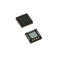
LDS8141-002-T2 IXYS, LDS8141-002-T2 Datasheet - Page 14

LDS8141-002-T2
Manufacturer Part Number
LDS8141-002-T2
Description
IC LED DRIVER WHIT BCKLGT 16WQFN
Manufacturer
IXYS
Series
LED-Sense™, Power-Lite™r
Type
Backlight, White LED (I²C Interface)r
Datasheet
1.LDS8141-002-T2.pdf
(22 pages)
Specifications of LDS8141-002-T2
Topology
High Side, Linear (LDO), PWM
Number Of Outputs
4
Internal Driver
Yes
Type - Primary
Backlight
Type - Secondary
White LED
Frequency
1.2MHz
Voltage - Supply
2.5 V ~ 5.5 V
Mounting Type
Surface Mount
Package / Case
16-WQFN, 16-miniQFN
Operating Temperature
-40°C ~ 85°C
Current - Output / Channel
32mA
Internal Switch(s)
Yes
Efficiency
80%
Lead Free Status / RoHS Status
Lead free / RoHS Compliant
Voltage - Output
-
Lead Free Status / Rohs Status
Details
Other names
LDS8141-002-T2-2
LDS8161/41
adjustment code for two 5ºC temperature steps in its
lower (bits 3:0) and higher (bits 7:4) nibble. User
loadable de-rating codes in the 1x scale mode
represent 0 to -7 PWM de-rating steps. In the 2 x
scale mode the de-rating codes represent 0 to -14
PWM steps.
Additionally, the LED drivers are disabled (i.e. 0 DC
current) if the measured LED junction temperature
exceeds a preset value that is loaded in register 4Ah.
The default is set for 1Ch = 105ºC Tj.
The LED-Sense
LED junction temperature on channel LEDA1 and
encodes the value into 5-bit T-codes representing
5
The measured T-code value addresses the stored
Δ PWM de-rating codes stored in the LUT registers to
© 2009 IXYS Corp.
Characteristics subject to change without notice
Figure 4: Dynamic Mode Dimming in Logarithmic
Figure 5: Dynamic Mode Dimming in Logarithmic
0
C temperature intervals from -35 to +120
Mode in percent vs. register 05h data
(0dB dimming = full LED brightness)
(0% dimming = full LED brightness)
Mode in dB vs. register 05h data
TM
engine periodically measures the
0
C.
14
adjust the PWM duty cycle. Therefore this reduces
the av erage current through the LEDs as defined by
the LUT table.
The user loads specific Δ PWM de-rating codes into
the LUT (56h – 5Dh) for every 5ºC temperature step
from 25ºC to 100ºC to meet desired current and
power vs. LED junction temperature.
LUT de-rating correction codes are subtracted from
the user-set duty cycle/dimming code (dynamic
mode) loaded in register 05h to maintain reliable LED
current levels.
The LDS8161/41 includes a 10-bit ADC and digital
processing engine to determine LED temperatures
approximately every 2.5 seconds. The proprietary
LED-Sense
LED junction temperatures on the LEDA1 driver
channel, without the need for an external temperature
sensor. Additionally an on-chip silicon temperature
sensing diode is also measured to enhance
temperature estimation accuracy.
Additionally, the ADC and processing circuits are
time-multiplexed to provide an LED opens and shorts
diagnostic feature.
A Factory loaded de-rating curve is valid upon reset,
and provide the de-rating profile shown at Figure 3.
I
The LDS8160 uses a 2-wire serial I
The SDAT and SCLK lines comply with the I
electrical specification and should be terminated with
pull-up resistors to the logic voltage supply. When the
bus is not used, both lines are high. The device
supports a maximum bus speed of 400kbit/s. The
serial
DEFINITION AND PROGRAMMING section for read
and write operations into the registers. Read and
write instructions are initiated by the master
controller/CPU and acknowledged by the slave LED
driver.
The LDS8161/41 allows user to choose between two
I
ground, or V
Table 11: LDS8161/41 I
For further details on the I
the I
393-40011, from Philips Semiconductors.
2
2
C Interface
C addresses by connecting SADD pin (#3) either to
2
C-Bus Specification, document number 9398-
SADD pin
connected to
Ground
V
bit
IN
TM
IN
sequence
algorithm allows direct measurement of
pin (see Table ).
2
I
Binary code
001 0001
101 0101
is
C Slave Addresses
2
Doc. No. 8141/61_DS, Rev. N1.0
C Address
2
C protocol, please refer to
shown
2
C-bus interface.
at
REGISTER
Hex
11h
55h
2
C


