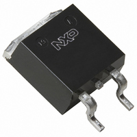
BUK135-50L,118 NXP Semiconductors, BUK135-50L,118 Datasheet - Page 4

BUK135-50L,118
Manufacturer Part Number
BUK135-50L,118
Description
TOPFET LOGIC LVL 50V D2PAK
Manufacturer
NXP Semiconductors
Series
TOPFET™r
Type
Low Sider
Datasheet
1.BUK135-50L118.pdf
(13 pages)
Specifications of BUK135-50L,118
Input Type
Non-Inverting
Number Of Outputs
1
On-state Resistance
21 mOhm
Current - Output / Channel
30A
Current - Peak Output
44A
Mounting Type
Surface Mount
Package / Case
D²Pak, TO-263 (4 leads + tab)
Lead Free Status / RoHS Status
Lead free / RoHS Compliant
Voltage - Supply
-
Operating Temperature
-
Other names
934056337118
BUK135-50L /T3
BUK135-50L /T3
BUK135-50L /T3
BUK135-50L /T3
Philips Semiconductors
PROTECTION SUPPLY CHARACTERISTICS
Limits are for -40˚C
OPEN CIRCUIT LOAD DETECTION CHARACTERISTICS
An open circuit load condition can be detected while the TOPFET is in the off-state. Refer to
V
OVERLOAD CHARACTERISTICS
T
1 When V
2 The drain source current which flows in a normal load when the protection supply is high and the input is low.
3 If V
4 For open circuit load detection, V
5 Trip time t
July 2002
Logic level TOPFET
SMD version of BUK124-50L
SYMBOL PARAMETER
V
I
V
V
t
SYMBOL PARAMETER
I
V
V
mb
SYMBOL PARAMETER
I
P
T
T
PS
PS
pr
DSP
D
DSC
j(TO)
PSF
(CL)PS
PSR
DSF
ISF
D(TO)
, I
= 5 V. Limits are for -40˚C
= 25˚C unless otherwise specified.
DS
PSL
< V
PS
DSF
d sc
is less than V
then the flag indicates open circuit load.
varies with overload dissipation P
Protection & detection
Threshold voltage
Normal operation or
protection latched
Supply current
Clamping voltage
Overload protection latched
Reset voltage
Reset time
Off-state drain current
Drain threshold voltage
Input threshold voltage
Short circuit load
Drain current limiting
Overload protection
Overload power threshold
Characteristic time
Overtemperature protection
Threshold temperature
PSF
T
mb
the flag pin indicates low protection supply voltage. Refer to TRUTH TABLE.
150˚C; typicals are for T
IS
must be less than V
1
T
mb
2
4
3
150˚C and typicals are for T
D
according to the formula t
ISF
CONDITIONS
I
V
I
V
CONDITIONS
V
V
I
CONDITIONS
V
V
V
device trips if P
which determines trip time
V
from I
.
F
P
D
PS
PS
IS
IS
PS
IS
PS
PS
= 100 A; V
= 1.5 mA
= 100 A
= 0 V; 2 V
= 0 V
= 5 V;
= 4.5 V
> 4 V
> 4 V
= 5 V
mb
1 V
D
= 25˚C.
4 A or V
4
d sc
DS
-40˚C
D
V
= 5 V
> P
DS
DS
T
DSC
> 0.2 V
mb
D(TO)
/ ln[ P
40 V
= 25˚C.
T
mb
5
D
/ P
150˚C
D(TO)
].
MIN.
MIN.
MIN.
28.5
250
150
2.5
5.5
0.9
0.2
0.3
10
75
1
-
TYP.
TYP.
TYP.
3.45
TRUTH TABLE
210
185
380
170
6.5
1.8
1.8
0.8
45
44
1
Product Specification
BUK135-50L
MAX.
MAX.
MAX.
450
120
250
600
8.5
2.7
1.1
60
4
3
2
-
.
Rev 1.100
UNIT
UNIT
UNIT
mA
˚C
W
V
V
V
V
V
A
A
s
s


