TB6560AHQ(O) Toshiba, TB6560AHQ(O) Datasheet - Page 32
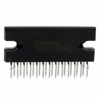
TB6560AHQ(O)
Manufacturer Part Number
TB6560AHQ(O)
Description
IC STEPPER MOTOR DRVR 2PH 25HZIP
Manufacturer
Toshiba
Type
Stepper Motor Driverr
Specifications of TB6560AHQ(O)
Applications
Stepper Motor Driver, 2 Phase
Number Of Outputs
1
Current - Output
3A
Voltage - Load
4.5 V ~ 34 V
Voltage - Supply
4.5 V ~ 5.5 V
Operating Temperature
-30°C ~ 85°C
Mounting Type
Through Hole
Package / Case
25-HZIP
Product
Stepper Motor Controllers / Drivers
Operating Supply Voltage
5 V
Mounting Style
SMD/SMT
Lead Free Status / RoHS Status
Lead free / RoHS Compliant
Other names
TB6560AHQO
TB6560HQ
TB6560HQ(O)
TB6560HQ
TB6560HQO
TB6560HQ
TB6560HQ(O)
TB6560HQ
TB6560HQO
Available stocks
Company
Part Number
Manufacturer
Quantity
Price
Company:

Part Number:
TB6560AHQ(O)
Manufacturer:
Toshiba
Quantity:
1 127
Company:
Part Number:
TB6560AHQ(O)
Manufacturer:
PJ
Quantity:
24


Notes on Contents
IC Usage Considerations
1. Block Diagrams
2. Equivalent Circuits
3. Timing Charts
4. Application Circuits
5. Test Circuits
Notes on Handling of ICs
Some of the functional blocks, circuits, or constants in the block diagram may be omitted or simplified for
explanatory purposes.
The equivalent circuit diagrams may be simplified or some parts of them may be omitted for explanatory
purposes.
Timing charts may be simplified for explanatory purposes.
The application circuits shown in this document are provided for reference purposes only. Thorough
evaluation is required, especially at the mass production design stage.
Toshiba does not grant any license to any industrial property rights by providing these examples of
application circuits.
Components in the test circuits are used only to obtain and confirm the device characteristics. These
components and circuits are not guaranteed to prevent malfunction or failure from occurring in the
application equipment.
(1)
(2)
(3)
(4)
The absolute maximum ratings of a semiconductor device are a set of ratings that must not be
exceeded, even for a moment. Do not exceed any of these ratings.
Exceeding the rating(s) may cause the device breakdown, damage or deterioration, and may result
injury by explosion or combustion.
Use an appropriate power supply fuse to ensure that a large current does not continuously flow in
case of over current and/or IC failure. The IC will fully break down when used under conditions that
exceed its absolute maximum ratings, when the wiring is routed improperly or when an abnormal
pulse noise occurs from the wiring or load, causing a large current to continuously flow and the
breakdown can lead smoke or ignition. To minimize the effects of the flow of a large current in case of
breakdown, appropriate settings, such as fuse capacity, fusing time and insertion circuit location, are
required.
If your design includes an inductive load such as a motor coil, incorporate a protection circuit into the
design to prevent device malfunction or breakdown caused by the current resulting from the inrush
current at power ON or the negative current resulting from the back electromotive force at power OFF.
IC breakdown may cause injury, smoke or ignition.
Use a stable power supply with ICs with built-in protection functions. If the power supply is unstable,
the protection function may not operate, causing IC breakdown. IC breakdown may cause injury,
smoke or ignition.
Do not insert devices in the wrong orientation or incorrectly.
Make sure that the positive and negative terminals of power supplies are connected properly.
Otherwise, the current or power consumption may exceed the absolute maximum rating, and
exceeding the rating(s) may cause the device breakdown, damage or deterioration, and may result
injury by explosion or combustion.
In addition, do not use any device that is applied the current with inserting in the wrong orientation
or incorrectly even just one time.
32
TB6560AHQ/AFG
2009-07-10
Related parts for TB6560AHQ(O)
Image
Part Number
Description
Manufacturer
Datasheet
Request
R

Part Number:
Description:
Toshiba Semiconductor [TOSHIBA IGBT Module Silicon N Channel IGBT]
Manufacturer:
TOSHIBA Semiconductor CORPORATION
Datasheet:
Part Number:
Description:
TOSHIBA GTR MODULE SILICON NPN TRIPLE DIFFUSED TYPE
Manufacturer:
TOSHIBA Semiconductor CORPORATION
Datasheet:
Part Number:
Description:
TOSHIBA GTR Module Silicon N Channel IGBT
Manufacturer:
TOSHIBA Semiconductor CORPORATION
Datasheet:
Part Number:
Description:
TOSHIBA Intelligent Power Module Silicon N Channel IGBT
Manufacturer:
TOSHIBA Semiconductor CORPORATION
Datasheet:
Part Number:
Description:
TOSHIBA INTELLIGENT POWER MODULE SILICON N CHANNEL LGBT
Manufacturer:
TOSHIBA Semiconductor CORPORATION
Datasheet:
Part Number:
Description:
TOSHIBA IGBT Module Silicon N Channel IGBT
Manufacturer:
TOSHIBA Semiconductor CORPORATION
Datasheet:
Part Number:
Description:
TOSHIBA GTR MODULE SILICON N−CHANNEL IGBT
Manufacturer:
TOSHIBA Semiconductor CORPORATION
Datasheet:
Part Number:
Description:
TOSHIBA Intelligent Power Module Silicon N Channel IGBT
Manufacturer:
TOSHIBA Semiconductor CORPORATION
Datasheet:
Part Number:
Description:
TOSHIBA GTR Module Silicon N Channel IGBT
Manufacturer:
TOSHIBA Semiconductor CORPORATION
Datasheet:
Part Number:
Description:
TOSHIBA INTELLIGENT POWER MODULE
Manufacturer:
TOSHIBA Semiconductor CORPORATION
Datasheet:
Part Number:
Description:
TOSHIBA Intelligent Power Module Silicon N Channel IGBT
Manufacturer:
TOSHIBA Semiconductor CORPORATION
Datasheet:
Part Number:
Description:
TOSHIBA Intelligent Power Module Silicon N Channel IGBT
Manufacturer:
TOSHIBA Semiconductor CORPORATION
Datasheet:
Part Number:
Description:
TOSHIBA IGBT Module Silicon N Channel IGBT
Manufacturer:
TOSHIBA Semiconductor CORPORATION
Datasheet:
Part Number:
Description:
TOSHIBA Intelligent Power Module Silicon N Channel IGBT
Manufacturer:
TOSHIBA Semiconductor CORPORATION
Datasheet:
Part Number:
Description:
Toshiba Semiconductor [SILICON N CHANNEL 1GBT]
Manufacturer:
TOSHIBA Semiconductor CORPORATION
Datasheet: