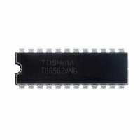
TB6562ANG Toshiba, TB6562ANG Datasheet - Page 4

TB6562ANG
Manufacturer Part Number
TB6562ANG
Description
IC DRIVER DUAL FULL BRDG 24SDIP
Manufacturer
Toshiba
Type
Full Bridge Motor Driverr
Datasheet
1.TB6562AFGOEL.pdf
(19 pages)
Specifications of TB6562ANG
Applications
Stepper Motor Driver, 2 Phase
Number Of Outputs
1
Current - Output
1.5A
Voltage - Supply
10 V ~ 34 V
Operating Temperature
-20°C ~ 85°C
Mounting Type
Through Hole
Package / Case
24-SDIP (0.300", 7.62mm)
Product
Stepper Motor Controllers / Drivers
Operating Supply Voltage
10 V to 34 V
Supply Current
12 mA
Mounting Style
Through Hole
Function
Driver
Vopmax (vm*)
34V (40V)
Io (lpeak)
(1.5A)
Excitation
1/4 step
I/f
phase input (2-bit/phase)
Mixed Decay Mode
no
Package
NDIP24
Rohs Compatible†
yes
Lead Free Status / RoHS Status
Lead free / RoHS Compliant
Voltage - Load
-
Lead Free Status / Rohs Status
Lead free / RoHS Compliant
Other names
TB6562ANG(O)
< TB6562AFG >
1
2
3
4
5
6
7
8
9
10
11
12
13
14
15
16
17
18
19
20
21
22
23
24
25
26
27
28
29
30
Pin No.
GND
Vreg
SB
Phase A
X1A
X2A
GND
GND
GND
Vcc
OUT1A
VrefA
RSA
OUT2A
GND
GND
OUT2B
RSB
VrefB
OUT1B
Vcc
GND
GND
GND
X2B
X1B
Phase B
OSC
V
GND
Symbol
CC
Ground pin
5 V output pin
Standby pin
Rotation direction control pin (Ch. A)
Input pin used to set output current level (Ch. A)
Input pin used to set output current level (Ch. A)
Ground pin
Ground pin
Ground pin
Power supply voltage input pin
Output pin 1 (Ch. A)
Reference voltage external set pin (Ch. A)
Resistance connect pin for detecting output current (Ch. A)
Output pin 2 (Ch. A)
Ground pin
Ground pin
Output pin 2 (Ch. B)
Output current detection resistor connection pin (Ch. B)
Input pin for external reference voltage (Ch. B)
Output pin 1 (Ch. B)
Power supply voltage input pin
Ground pin
Ground pin
Ground pin
Input pin used to set output current level (Ch. B)
Input pin used to set output current level (Ch. B)
Rotation direction control pin (Ch. B)
External capacitor pin for triangular-wave oscillation
Power supply voltage input pin
Ground pin
Function Description
4
Connect a capacitor between this pin and the GND pin.
H: start, L: Standby, Built-in pull down resistance of
100kΩ(typ.)
Apply a 0 V / 5 V signal, Built-in pull down resistance
of 100kΩ(typ.)
Apply a 0 V / 5 V signal, Built-in pull down resistance
of 100kΩ(typ.)
Apply a 0 V / 5 V signal, Built-in pull down resistance
of 100kΩ(typ.)
Vcc (opr) = 10 V to 34 V
Vcc (opr) = 10 V to 34 V
Apply a 0 V / 5 V signal, Built-in pull down resistance
of 100kΩ(typ.)
Apply a 0 V / 5 V signal, Built-in pull down resistance
of 100kΩ(typ.)
Apply a 0 V / 5 V signal, Built-in pull down resistance
of 100kΩ(typ.)
V
Connect to a motor coil pin.
Connect to a motor coil pin.
Connect to a motor coil pin.
Connect to a motor coil pin.
CC (opr)
= 10 V to 34 V
TB6562ANG/AFG
Remarks
2007-3-22


