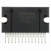
TB6581HG Toshiba, TB6581HG Datasheet - Page 6

TB6581HG
Manufacturer Part Number
TB6581HG
Description
IC BRUSHLESS MOTOR CTLR 25HZIP
Manufacturer
Toshiba
Type
3 Phase Full Wave Sine Wave PWM Brushless Motor Controllerr
Datasheet
1.TB6581HG.pdf
(15 pages)
Specifications of TB6581HG
Applications
DC Motor Controller, Brushless (BLDC), 3 Phase
Number Of Outputs
1
Current - Output
1A
Voltage - Load
50 V ~ 400 V
Voltage - Supply
13.5 V ~ 16.5 V
Operating Temperature
-30°C ~ 115°C
Mounting Type
Through Hole
Package / Case
25-HZIP
Product
Fan / Motor Controllers / Drivers
Operating Supply Voltage
15 V, 7 V
Supply Current
3 mA, 6 mA
Mounting Style
SMD/SMT
Lead Free Status / RoHS Status
Lead free / RoHS Compliant
Available stocks
Company
Part Number
Manufacturer
Quantity
Price
Company:
Part Number:
TB6581HG
Manufacturer:
Toshiba
Quantity:
10
Company:
Part Number:
TB6581HG
Manufacturer:
NORTEL
Quantity:
89
Part Number:
TB6581HG
Manufacturer:
TOSHIBA/东芝
Quantity:
20 000
Functional Description
1. Basic operation
2. V
3. Dead time function: upper/lower transistor output off-time
4. Correcting the lead angle
Note 1: At startup, the low-side IGBTs must be turned on for a fixed period at 1.0 V < V
signal reaches number of rotations f = 5 Hz or higher, the rotor position is estimated according to the
positional signal and a modulation wave is generated. The modulation wave and the triangular wave are
compared; then the sine-wave PWM signal is generated and the motor is driven.
(1)
(2)
(3)
short circuit caused by the simultaneously turning on of upper and lower external power devices. When a
square wave is generated in full-duty cycle mode, the dead time function is turned on to prevent a short
circuit.
voltage.
e
The motor is driven by the square-wave turn-on signal based on a positional signal. When the positional
When the motor is driven by sine-wave PWM, dead time is digitally generated inside the IC to prevent
T
f
The lead angle can be corrected in the turn-on signal range from 0 to 58° in relation to the induced
Analog input from LA pin (0 V to 5 V divided by 32)
osc
Internal Counter
voltage command input and bootstrap power supply
OFF
From start to 5 Hz: When driven by square wave (120° turn-on) f = f
5 Hz~: When driven by sine-wave PWM (180° turn-on); when f
0 V = 0°
5 V = 58° (when more than 5 V is input, 58°)
Voltage command input: When V
Voltage command input: When 1.0 V < V
Voltage command input: When V
(duty cycle: 8%).
= reference clock (crystal oscillation)
U, V and W signals are stopped to protect IGBTs
The low-side IGBTs are turned on at a fixed frequency (carrier frequency) (duty cycle: 8%).
The U, V and W signals are driven out during sine wave drive.
The low-side IGBTs are forced to on at fixed frequency (carrier frequency) during square-wave drive
8/f
values above are obtained when fosc = 4.19 MHz.
PWM duty cycle
high-side IGBT power supply.
100%
osc
(1)
1.0 V
(2)
1.9 µs
T
2.1 V
OFF
(3)
5.4 V
e
e
< = 1.0 V
> 2.1 V
e
< = 2.1 V
V e
6
(1) 0 to 1.0 V: Reset state (All outputs are off.)
(2) V e = 1.0 to 2.1 V: Startup operation
(3) V e = 2.1 to 5.4 V: Running state
(duty cycle of 8% for the low-side IGBTs)
(5.4 V or higher: PWM duty cycle = 100%)
osc
= 4 MHz, approx. 5 Hz
osc
/(2
12
× 32 × 6)
e
< = 2.1 V to charge the
TB6581H/HG
2006-03-02


