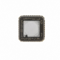
TB6557FLG(EL) Toshiba, TB6557FLG(EL) Datasheet

TB6557FLG(EL)
Specifications of TB6557FLG(EL)
Related parts for TB6557FLG(EL)
TB6557FLG(EL) Summary of contents
Page 1
... TOSHIBA BiCD Integrated Circuit Silicon Monolithic DC Motor Driver The TB6557FLG is a driver IC for driving DC motors. Its employs LDMOS devices with low ON resistance for output drive transistors. The TB6557FLG incorporates two constant current-controlled H-bridge drivers and four voltage-controlled H-bridge drivers, making it ideal for controlling Zoom/AF/IRIS lens motors in digital still cameras and camcorders ...
Page 2
Block Diagram GND UVLO CK 6 Serial decoder + DATA 5 Address selector LD 4 PWMA 36 PWMB 27 PWMC 20 PWMD 19 Band gap Vref (0.3 V) Vref 23 PWME 28 VC1 26 OSC OSC ...
Page 3
Absolute Maximum Ratings Characteristics Supply voltage Motor supply voltage Output pin voltage Output current Input voltage Power dissipation Operating temperature Storage temperature Recommended Operating Conditions Characteristics Small signal supply voltage Motor supply voltage Output current PWM frequency OSC oscillation frequency ...
Page 4
Recommended Operating Conditions 2: Serial Data Controller Characteristics Low-level clock pulse width High-level clock pulse width Clock rise time Clock fall time Data setup time Data hold time Load setup time Load hold time High-level load pulse width Latch output ...
Page 5
Specifications and Operation of Each Circuit Block: • Bridge output block: PWM control feature While PWM control is applied, normal operation t1, t5, and short brake t3 are repeated. (Dead time t2 and t4 are inserted to prevent pass-through current.) ...
Page 6
Operation of OSC oscillator: Charging and discharging external capacitor when charging OSC ON when discharging OSC block In the above circuit configuration, the voltage inclination represented as follows: OSC ∫ i ...
Page 7
Constant-current bridge block (H-SW E, F): Description of PWM constant-current chopping Turning on the power (Chop on) causes current to flow into the load inductor. Once the voltage (VRF) generated with the external current detection resistor reaches the comparator ...
Page 8
Serial Data Specifications: 9-bit serial data Last Data Register modes mod2 mod1 mod4 mod3 mod6 mod5 pwm6 pwm5 ...
Page 9
Serial Decoder Block Diagram 6-bit latch H-SW Logic IN1 Example Timing Chart Latch The 9-bit serial data, input to the DA pin, is detected on the rising edge ...
Page 10
Electrical Characteristics (V Characteristics Supply current Input voltage Serial/standby input Input current Input voltage PWM input Input current Output saturation voltage Output leakage current Output diode forward voltage Internal reference voltage Offset voltage for constant-current detection comparator Reference oscillation frequency ...
Page 11
Example Application Circuit Control power C1 C2 supply ( 2.7~5.5 V GND DATA STBY 10 PWMA 36 PWMB 27 PWMC 20 PWMD MPU 19 Vref 23 PWME 28 VC1 26 C6 OSC ...
Page 12
Requests Concerning Use of QON Outline Drawing of Package (Upper surface) When using QON, please take into account the following items. Caution (1) Do not carry out soldering on the island section in the four corners of the package (the ...
Page 13
Package Dimensions Weight: 0.08 g (typ.) 13 TB6557FLG 2006-6-26 ...
Page 14
... Application Circuits The application circuits shown in this document are provided for reference purposes only. Thorough evaluation is required, especially at the mass production design stage. Toshiba does not grant any license to any industrial property rights by providing these examples of application circuits. 5. Test Circuits Components in the test circuits are used only to obtain and confirm the device characteristics. These components and circuits are not guaranteed to prevent malfunction or failure from occurring in the application equipment ...
Page 15
Points to remember on handling of ICs (1) Thermal Shutdown Circuit Thermal shutdown circuits do not necessarily protect ICs under all circumstances. If the thermal shutdown circuits operate against the over temperature, clear the heat generation status immediately. Depending on ...
Page 16
TB6557FLG 2006-6-26 ...


