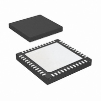
LP3913SQ-AR/NOPB National Semiconductor, LP3913SQ-AR/NOPB Datasheet - Page 12

LP3913SQ-AR/NOPB
Manufacturer Part Number
LP3913SQ-AR/NOPB
Description
IC PMU FLASH MEM PROGRMMBL 48LLP
Manufacturer
National Semiconductor
Series
PowerWise®r
Datasheet
1.LP3913SQ-ACNOPB.pdf
(58 pages)
Specifications of LP3913SQ-AR/NOPB
Applications
Handheld/Mobile Devices
Voltage - Supply
2.5 V ~ 6 V
Operating Temperature
-40°C ~ 85°C
Mounting Type
Surface Mount
Package / Case
48-LLP
Lead Free Status / RoHS Status
Lead free / RoHS Compliant
Current - Supply
-
Other names
LP3913SQ-ARTR
www.national.com
V
RANGE 0
V
RANGE 1
ADC1 &
ADC2
ADC1 &
ADC2
t
t
CONV
WARM
ISENSE
ISENSE
Note 1: Absolute Maximum Ratings indicate limits beyond which damage to the component may occur. Operating Ratings are conditions under which operation
of the device is guaranteed. Operating Ratings do not imply guaranteed performance limits. For guaranteed performance limits and associated test conditions,
see the Electrical Characteristics tables.
Note 2: All voltages are with respect to the potential at the GND pin.
Note 3: Internal thermal shutdown circuitry protects the device from permanent damage. Thermal shutdown engages at T
= 140°C (typ.).
Note 4: The Human body model is a 100 pF capacitor discharged through a 1.5 kΩ resistor into each pin. The machine model is a 200 pF capacitor discharged
directly into each pin. MIL-STD-883 3015.7.
Note 5: In applications where high power dissipation and/or poor package thermal resistance is present, the maximum ambient temperature may have to be
derated. Maximum ambient temperature (T
dissipation of the device in the application (P
following equation: T
Note 6: Junction-to-ambient thermal resistance is highly application and board-layout dependent. In applications where high maximum power dissipation exists,
special care must be paid to thermal dissipation issues in board design.
Note 7: Min and Max limits are guaranteed by design, test, or statistical analysis. Typical numbers are not guaranteed, but do represent the most likely norm.
Note 8: Low ESR Surface-Mount Ceramic Capacitors (MLCCs) are used in setting electrical characteristics.
Note 9: Specifications guaranteed by design. Not tested during production.
Note 10: Typical values and limits appearing in normal type for T
for operation, −40°C to +125°C.
Note 11: LDO2EN, BUCK1EN, and USBSUSP have weak internal pull downs while pins POWERACK, ONOFF do not have this.
Symbol
MAX
MIN
ISENSE Max Voltage Scalar Output
ISENSE Min Voltage Scalar Output
ISENSE Max Voltage Scalar Output
ISENSE Min Voltage Scalar Output
ADC1 & ADC2 Min Voltage Scalar Output V
ADC1 & ADC2 Max Voltage Scalar
Output
Conversion Time
Warm-up Time
A-MAX
= T
J-MAX-OP
Parameter
− (θ
JA
A-MAX
D-MAX
× P
) is dependent on the maximum operating junction temperature (T
D-MAX
), and the junction-to-ambient thermal resistance of the part/package in the application (θ
).
J
= 25°C. Limits appearing in boldface type apply over the entire junction temperature range
V
(I
R
V
(I
R
V
(I
R
V
R
V
(Note 9)
CHG
CHG
CHG
ISENSE
ISENSE
ISENSE
ISENSE
REFH
REFH
SENSE
SENSE
SENSE
SENSE
= 0.605A,
= 0A,
= 1.1A,
= 1.225
= 1.225
= 4.64 kΩ)
= 4.64 kΩ)
= 4.64 kΩ)
= 4.64 kΩ)
= 0.6463V
= 0V
= 1.175V
= 0V (I
12
Conditions
CHG
= 0A,
J-MAX-OP
2.373
1.186
2.373
1.186
1.218
2.436
Min
J
= 125°C), the maximum power
= 160°C (typ.) and disengages at T
1.225
1.225
1.225
2.45
2.45
2.45
Typ
2
JA
), as given by the
2.519
1.260
2.519
1.260
1.230
Max
2.46
5
Units
ms
ms
V
V
V
V
V
V
J


