L9953 STMicroelectronics, L9953 Datasheet - Page 21
L9953
Manufacturer Part Number
L9953
Description
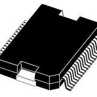
IC DVR DOOR ACTUATOR POWERSO-36
Manufacturer
STMicroelectronics
Datasheet
1.L9953XPTR.pdf
(38 pages)
Specifications of L9953
Applications
Door Actuator
Current - Supply
7mA
Voltage - Supply
7 V ~ 28 V
Operating Temperature
-40°C ~ 150°C
Mounting Type
Surface Mount
Package / Case
PowerSO-36 Exposed Bottom Pad
Mounting Style
SMD/SMT
Lead Free Status / RoHS Status
Lead free / RoHS Compliant
Available stocks
Company
Part Number
Manufacturer
Quantity
Price

Part Number:
L9953EXP
Manufacturer:
ST
Quantity:
20 000
Part Number:
L9953LXP
Manufacturer:
ST
Quantity:
20 000
Part Number:
L9953LXPTR
Manufacturer:
ST
Quantity:
20 000
Part Number:
L9953XP
Manufacturer:
ST
Quantity:
20 000
Company:
Part Number:
L9953XPTR
Manufacturer:
st
Quantity:
1 699
Part Number:
L9953XPTR
Manufacturer:
ST
Quantity:
20 000


L9953 / L9953XP
3.10
3.11
3.12
3.13
Current monitor
The current monitor output sources a current image at the current monitor output which has
a fixed ratio (1/10000) of the instantaneous current of the selected highside driver. The bits
18 and 19 of the Input Data Register 0 control which of the outputs OUT1, OUT4, OUT5,
and OUT8 will be multiplexed to the current monitor output. The current monitor output
allows a more precise analysis of the actual state of the load rather than the detection of an
open- or overload condition. For example this can be used to detect the motor state
(starting, free-running, stalled). Moreover, it is possible to regulate the power of the defroster
more precise by measuring the load current. The current monitor output is bidirectional (c.f.
PWM inputs).
PWM inputs
Each driver has a corresponding PWM enable bit which can be programmed by the SPI
interface. If the PWM enable bit in Input Data Register 1 is set, the output is controlled by the
logically AND-combination of the PWM signal and the output control bit in Input Data
Register 0. The outputs OUT1-OUT6 and OUT8 are controlled by the PWM1 input and the
output OUT7 is controlled by the bidirectional input CM/PMW2. For example, the two PWM
inputs can be used to dim two lamps independently by external PWM signals.
Cross-current protection
The six half-bridges of the device are cross-current protected by an internal delay time. If
one driver (LS or HS) is turned-off the activation of the other driver of the same half bridge
will be automatically delayed by the cross-current protection time. After the cross-current
protection time is expired the slew-rate limited switch-off phase of the driver will be changed
to a fast turn-off phase and the opposite driver is turned-on with slew-rate limitation. Due to
this behavior it is always guaranteed that the previously activated driver is totally turned-off
before the opposite driver will start to conduct.
Programmable softstart function to drive loads with higher
inrush current
Loads with start-up currents higher than the over-current limits (e.g. inrush current of lamps,
start current of motors and cold resistance of heaters) can be driven by using the
programmable softstart function (i.e. overcurrent recovery mode). Each driver has a
corresponding over-current recovery bit. If this bit is set, the device will automatically switch-
on the outputs again after a programmable recovery time. The duty cycle in over-current
condition can be programmed by the SPI interface to be about 12% or 25%. The PWM
modulated current will provide sufficient average current to power up the load (e.g. heat up
the bulb) until the load reaches operating condition. The PWM frequency settles at 3kHz or
6kHz. The device itself cannot distinguish between a real overload and a non linear load like
a light bulb. A real overload condition can only be qualified by time. As an example the
microcontroller can switch on light bulbs by setting the over-current Recovery bit for the first
50ms. After clearing the recovery bit the output will be automatically disabled if the overload
condition still exits.
Doc ID 14278 Rev 3
Application information
21/38
Related parts for L9953
Image
Part Number
Description
Manufacturer
Datasheet
Request
R

Part Number:
Description:
STMicroelectronics [RIPPLE-CARRY BINARY COUNTER/DIVIDERS]
Manufacturer:
STMicroelectronics
Datasheet:
Part Number:
Description:
STMicroelectronics [LIQUID-CRYSTAL DISPLAY DRIVERS]
Manufacturer:
STMicroelectronics
Datasheet:

Part Number:
Description:
BOARD EVAL FOR MEMS SENSORS
Manufacturer:
STMicroelectronics
Datasheet:
Part Number:
Description:
NPN TRANSISTOR POWER MODULE
Manufacturer:
STMicroelectronics
Datasheet:
Part Number:
Description:
TURBOSWITCH ULTRA-FAST HIGH VOLTAGE DIODE
Manufacturer:
STMicroelectronics
Datasheet:
Part Number:
Description:
Manufacturer:
STMicroelectronics
Datasheet:
Part Number:
Description:
DIODE / SCR MODULE
Manufacturer:
STMicroelectronics
Datasheet:
Part Number:
Description:
DIODE / SCR MODULE
Manufacturer:
STMicroelectronics
Datasheet:
Part Number:
Description:
Search -----> STE16N100
Manufacturer:
STMicroelectronics
Datasheet:
Part Number:
Description:
Search ---> STE53NA50
Manufacturer:
STMicroelectronics
Datasheet:
Part Number:
Description:
NPN Transistor Power Module
Manufacturer:
STMicroelectronics
Datasheet:
Part Number:
Description:
DIODE / SCR MODULE
Manufacturer:
STMicroelectronics
Datasheet: