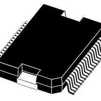
L9953 STMicroelectronics, L9953 Datasheet - Page 25

L9953
Manufacturer Part Number
L9953
Description
IC DVR DOOR ACTUATOR POWERSO-36
Manufacturer
STMicroelectronics
Datasheet
1.L9953XPTR.pdf
(38 pages)
Specifications of L9953
Applications
Door Actuator
Current - Supply
7mA
Voltage - Supply
7 V ~ 28 V
Operating Temperature
-40°C ~ 150°C
Mounting Type
Surface Mount
Package / Case
PowerSO-36 Exposed Bottom Pad
Mounting Style
SMD/SMT
Lead Free Status / RoHS Status
Lead free / RoHS Compliant
Available stocks
Company
Part Number
Manufacturer
Quantity
Price
Part Number:
L9953EXP
Manufacturer:
ST
Quantity:
20 000
Part Number:
L9953LXP
Manufacturer:
ST
Quantity:
20 000
Part Number:
L9953LXPTR
Manufacturer:
ST
Quantity:
20 000
Part Number:
L9953XP
Manufacturer:
ST
Quantity:
20 000
Company:
Part Number:
L9953XPTR
Manufacturer:
st
Quantity:
1 699
Part Number:
L9953XPTR
Manufacturer:
ST
Quantity:
20 000
L9953 / L9953XP
4.9
Table 18.
OUT1
PWM
1 EN
! (both HI)
! (both HI)
! (both HI)
! (both HI)
both HI
both HI
both HI
both HI
OUT2
PWM
1 EN
Test mode
The Test Mode can be entered by rising the CSN input to a voltage higher than 9.5V. In the
test mode the inputs CLK, DI, PWM1/2, the internal 2MHz CLK, OL and OC can be
multiplexed to output DO and Iref, Tsens1-4 and Vbgp can be multiplexed to input
CM/PWM2.
Furthermore the over-current thresholds are reduced by a factor of 4 to allow EWS testing at
lower current.
The internal logic prevents that the High-Side and Low-Side driver of the same half-bridge
can be switched-on at the same time. In the test mode this combination is used to multiplex
the desired signals according to following table:
Test mode
OUT3
PWM
1 EN
! (both HI)
! (both HI)
! (both HI)
! (both HI)
both HI
both HI
both HI
both HI
OUT4
PWM
1 EN
OUT5
PWM
1 EN
! (both HI)
! (both HI)
! (both HI)
! (both HI)
both HI
both HI
both HI
both HI
OUT6
PWM
1 EN
INT_CLK
NoError
PWM1
PWM2
CLK
OC
OL
DO
DI
Doc ID 14278 Rev 3
LS3
! (both HI)
! (both HI)
! (both HI)
! (both HI)
both HI
both HI
both HI
both HI
HS3
LS4
! (both HI)
! (both HI)
! (both HI)
! (both HI)
both HI
both HI
both HI
both HI
Functional description of the SPI
HS4
LS5
! (both HI)
! (both HI)
! (both HI)
! (both HI)
both HI
both HI
both HI
both HI
HS5
Vbandgap
Test Pad
5µA Iref
Tsens1
Tsens2
Tsens3
Tsens4
x
x
25/38


