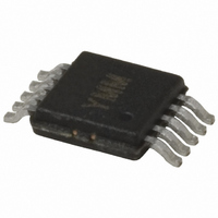
MIC2169BYMM Micrel Inc, MIC2169BYMM Datasheet - Page 14

MIC2169BYMM
Manufacturer Part Number
MIC2169BYMM
Description
IC CTLR PWM BUCK SYNC 10MSOP
Manufacturer
Micrel Inc
Datasheet
1.MIC2169BYMM.pdf
(25 pages)
Specifications of MIC2169BYMM
Pwm Type
Voltage Mode
Number Of Outputs
1
Frequency - Max
550kHz
Duty Cycle
92%
Voltage - Supply
3 V ~ 14.5 V
Buck
Yes
Boost
No
Flyback
No
Inverting
No
Doubler
No
Divider
No
Cuk
No
Isolated
No
Operating Temperature
-40°C ~ 85°C
Package / Case
10-MSOP, Micro10™, 10-uMAX, 10-uSOP
Frequency-max
550kHz
Lead Free Status / RoHS Status
Lead free / RoHS Compliant
Other names
576-3641-5
MIC2169BYMM
MIC2169BYMM
Available stocks
Company
Part Number
Manufacturer
Quantity
Price
Part Number:
MIC2169BYMM
Manufacturer:
MICREL/麦瑞
Quantity:
20 000
Depending on the circuit components and operating
conditions, an external Schottky diode will give a ½% to
1% improvement in efficiency.
Feedback Loop Compensation
The MIC2169B controller comes with an internal
transconductance error amplifier used for compensating
the voltage feedback loop by placing a capacitor (C1) in
series with a resistor (R1) and another capacitor C2 in
parallel from the COMP pin to ground. See “Functional
Block Diagram.”
Power Stage
The power stage of a voltage mode controller has an
inductor,
connected to the output capacitor, C
electrical series resistance (ESR) as shown in Figure 7.
The transfer function G(s), for such a system is:
Plotting this transfer function with the following assumed
values
ESR=0.025Ω) gives lot of insight as to why one needs to
compensate the loop by adding resistor and capacitors
on the COMP pin. Figures 8 and 9 show the gain curve
and phase curve for the above transfer function.
Micrel, Inc.
April 2010
Figure 7. The Output LC Filter in a Voltage-Mode Buck
G
(
) s
=
L1,
⎛
⎜ ⎜
⎝
(L=1μH,
Figure 8. The Gain Curve for G(s)
DCR
with
×
s
×
L
C
its
Converter
(
+
DCR=0.009Ω,
1
s
+
2
winding
ESR
×
DCR
L
×
×
C
s
ESR
+
×
C
1
C
resistance
OUT
+
)
ESR
V
O
OUT
C
×
OUT
, with its
s
×
=660μF,
C
(DCR)
⎞
⎟ ⎟
⎠
14
It can be seen from the transfer function G(s) and the
gain curve that the output inductor and capacitor create
a two pole system with a break frequency at:
Therefore, f
By looking at the phase curve, it can be seen that the
output capacitor ESR (0.025Ω) cancels one of the two
poles (LC
Therefore, F
From the point of view of compensating the voltage loop,
it is recommended to use higher ESR output capacitors
since they provide a 90° phase gain in the power path.
For comparison purposes, Figure 10, shows the same
phase curve with an ESR value of 0.002Ω.
f
f
LC
ZERO
Figure 10. The Phase Curve with ESR = 0.002 Ω
=
OUT
2
=
LC
×
ZERO
) system by introducing a zero at:
2
π
Figure 9. Phase Curve for G(s)
= 6.2kHz
×
L
π
= 9.6kHz.
1
×
×
C
ESR
OUT
1
×
C
OUT
M9999-041210-B
MIC2169B


