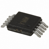
MIC2169BYMM Micrel Inc, MIC2169BYMM Datasheet - Page 18

MIC2169BYMM
Manufacturer Part Number
MIC2169BYMM
Description
IC CTLR PWM BUCK SYNC 10MSOP
Manufacturer
Micrel Inc
Datasheet
1.MIC2169BYMM.pdf
(25 pages)
Specifications of MIC2169BYMM
Pwm Type
Voltage Mode
Number Of Outputs
1
Frequency - Max
550kHz
Duty Cycle
92%
Voltage - Supply
3 V ~ 14.5 V
Buck
Yes
Boost
No
Flyback
No
Inverting
No
Doubler
No
Divider
No
Cuk
No
Isolated
No
Operating Temperature
-40°C ~ 85°C
Package / Case
10-MSOP, Micro10™, 10-uMAX, 10-uSOP
Frequency-max
550kHz
Lead Free Status / RoHS Status
Lead free / RoHS Compliant
Other names
576-3641-5
MIC2169BYMM
MIC2169BYMM
Available stocks
Company
Part Number
Manufacturer
Quantity
Price
Part Number:
MIC2169BYMM
Manufacturer:
MICREL/麦瑞
Quantity:
20 000
MOSFETs
•
RC Snubber
•
Schottky Diode (Optional)
•
•
•
Evaluation Board Schematics
Micrel, Inc.
April 2010
Low gate charge MOSFETs should be used to
maximize efficiency, such as Si4800, Si4804BDY,
IRF7821, IRF8910, FDS6680A and FDS6912A, etc.
Add a RC snubber of 1.4Ω resistor and a 1000pF
capacitor from the switch node to ground pin. Place
the snubber on the same side of the board and as
close to the MOSFETs as possible. See page 8,
Current Limiting section for more detail.
Place the Schottky diode on the same side of the
board as the MOSFETs and V
The connection from the Schottky diode’s Anode to
the input capacitors ground terminal must be as
short as possible.
The diode’s Cathode connection to the switch node
(SW) must be keep as short as possible.
IN
input capacitor.
MIC2169B Evaluation Board Schematic
18
Others
•
•
•
•
Connect the current limiting (R2) resistor directly to
the drain of top MOSFET Q3.
The feedback resistors R3 and R4/R5/R6 should be
placed close to the FB pin. The top side of R3
should connect directly to the output node. Run this
trace away from the switch node (junction of Q3, Q2,
and L1). The bottom side of R3 should connect to
the GND pin on the MIC2169B.
The compensation resistor and capacitors should be
placed right next to the COMP pin and the other side
should connect directly to the GND pin on the
MIC2169B rather than going to the plane.
Add a place holder for a gate resistor on the top
MOSFET gate drive. Do not use a resistor in series
with the low-side MOSFET gate.
M9999-041210-B
MIC2169B


