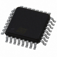
L5994 STMicroelectronics, L5994 Datasheet - Page 17

L5994
Manufacturer Part Number
L5994
Description
IC CTRLR PS ADJ TRPL-OUT 32-TQFP
Manufacturer
STMicroelectronics
Datasheet
1.L5994.pdf
(26 pages)
Specifications of L5994
Pwm Type
Current Mode
Number Of Outputs
3
Frequency - Max
345kHz
Duty Cycle
96%
Voltage - Supply
4.75 V ~ 25 V
Buck
Yes
Boost
No
Flyback
Yes
Inverting
No
Doubler
No
Divider
No
Cuk
No
Isolated
No
Operating Temperature
-40°C ~ 140°C
Package / Case
32-TQFP, 32-VQFP
Frequency-max
345kHz
Lead Free Status / RoHS Status
Lead free / RoHS Compliant
Available stocks
Company
Part Number
Manufacturer
Quantity
Price
Input Capacitors
A pulsed current (with zero average value) flows through the input capacitor of a buck converter. The AC com-
ponent of this current is quite high and dissipates a considerable amount of power on the ESR of the capacitor:
It is easy to find that PCIN has a maximum equal to IOUT/2 (@ VIN=2×VOUT, that is, 50% duty cycle). The
input capacitor of each section, therefore, should be selected for a RMS ripple current rating as high as half the
respective maximum output current. The capacitance value is not very important but in reality a minimum value
must be ensured for stability reasons. In fact, switching regulators exhibit a negative input impedance that, at
low frequencies, is:
thus, if the impedance of the power source is not well below the absolute value of Z
the bandwidth of the regulator control loop, there is the possibility for oscillations. To ensure stability, the follow-
ing condition must be satisfied:
where L
input capacitor itself.The use of high performance electrolytic capacitors is recommended. If a higher cost is of
no concern, OS-CON capacitors are an excellent choice because they offer the smallest size for a given ESR
or current rating. Tantalum capacitors do not tolerate pulsed current, so their use is not advisable.
Output Capacitors
The output capacitor selection is based on the output voltage ripple requirements. This ripple is related to the
current ripple through the inductor and is almost entirely due to the ESR of the output capacitor. Therefore, the
goal is to achieve an ESR lower than a certain value, regardless of the actual capacitance value.
The maximum current ripple of the +3.3V section is:
considering the values obtained in the paragraph "+3.3V inductor". As for the +5.1V, the maximum ripple is giv-
en by:
where V
Anyhow, the maximum ESR will be:
where the subscript x refers to either section.
In pulse-skipping operation, the capacitive component of the output ripple is comparable to the resistive one,
EQ
IN
is V
is the inductance of the circuit upstream the switching regulator input and ESR
INMIN
or V
INMAX
, as selected in the "+5.1 transformer" section.
I
L5
Pc
=
IN
=
I
OUT 12
ESR I
Z
C
IN DC
IN
I
L3
ESR
»
= 2 · (I
---------------------------------------------- -
ESR
2
OUT
-----------------------
V
IN
=
X
V
IN
–
IN
L3PK
------------------------------- -
V
V
------------------------------------------------------ -
5.1
V
----------------- -
L
OUT
OUT
EQ
RPKX
Z
I
V
- I
LX
+
IN DC
2
IN
OUT3
3
-- -
4
I
OUT
V
V
5.1
---------------------------------------- -
f
IN
2
IN
)
SW
–
V
V
L
OUT
IN
3 P
–
V
5.1
IN
IN(DC)
at frequencies up to
L5994 - L5994A
IN
is related to the
17/26


