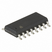
ISL6722AABZ Intersil, ISL6722AABZ Datasheet - Page 20

ISL6722AABZ
Manufacturer Part Number
ISL6722AABZ
Description
IC CTRLR PWM SGL ENDED 16-SOIC
Manufacturer
Intersil
Datasheet
1.ISL6722AAVZ.pdf
(24 pages)
Specifications of ISL6722AABZ
Pwm Type
Current Mode
Number Of Outputs
1
Frequency - Max
1MHz
Duty Cycle
100%
Voltage - Supply
9 V ~ 18 V
Buck
Yes
Boost
Yes
Flyback
Yes
Inverting
No
Doubler
No
Divider
No
Cuk
No
Isolated
Yes
Operating Temperature
-40°C ~ 105°C
Package / Case
16-SOIC (3.9mm Width)
Frequency-max
1MHz
Lead Free Status / RoHS Status
Lead free / RoHS Compliant
Available stocks
Company
Part Number
Manufacturer
Quantity
Price
Part Number:
ISL6722AABZ
Manufacturer:
INTERSIL
Quantity:
20 000
Part Number:
ISL6722AABZ-T
Manufacturer:
INTERS
Quantity:
20 000
Waveforms
Typical waveforms can be found in Figures 13 through 15.
These waveforms are taken from an ISL6721EVAL1
evaluation board, and therefore include synchronization
waveforms that are not applicable to the ISL6722A, but are
otherwise representative. Figure 13 shows the steady state
operation of the sawtooth oscillator waveform at RTCT
(Trace 2), the SYNC output pulse (Trace 1), and the GATE
output to the converter FET (Trace 3). Figure 14 shows the
converter behavior while operating in an overcurrent fault
condition. Trace 1 is the soft-start voltage, which increases
from zero to 4.5V, at which point the OC fault function is
enabled. The OC condition is detected and the soft-start
capacitor is discharged to the 4.375V OC fault threshold at
which point the IC enters the fault shutdown mode. Trace 2
shows the behavior of the timing capacitor voltage during a
shutdown fault. Most of the functions of the IC are de-
powered during a fault, and the oscillator is among those
functions. During a fault, the IC is turned off until the restart
delay has timed out. After the delay, power is restored and
the IC resumes normal operation. Trace 3 is the GATE
output during the soft-start cycle and OC fault.
NOTE:
Trace 1: SYNC Output
Trace 2: RTCT Sawtooth
Trace 3: GATE Output
FIGURE 13. TYPICAL WAVEFORMS
20
ISL6722A, ISL6723A
Figure 15 shows the switching FET waveforms during
steady state operation. Trace 1 is drain - source voltage and
Trace 2 is gate - source voltage.
NOTE:
NOTE:
Trace 1: V
Trace 3: V
Trace 1: SS
Trace 2: RTCT Sawtooth
Trace 3: GATE Output
FIGURE 14. SOFT-START WITH OVERCURRENT FAULT
FIGURE 15. GATE AND DRAIN-SOURCE WAVEFORMS
D-S
G-S
July 11, 2007
FN9237.1


