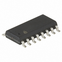
ISL6722AABZ Intersil, ISL6722AABZ Datasheet - Page 8

ISL6722AABZ
Manufacturer Part Number
ISL6722AABZ
Description
IC CTRLR PWM SGL ENDED 16-SOIC
Manufacturer
Intersil
Datasheet
1.ISL6722AAVZ.pdf
(24 pages)
Specifications of ISL6722AABZ
Pwm Type
Current Mode
Number Of Outputs
1
Frequency - Max
1MHz
Duty Cycle
100%
Voltage - Supply
9 V ~ 18 V
Buck
Yes
Boost
Yes
Flyback
Yes
Inverting
No
Doubler
No
Divider
No
Cuk
No
Isolated
Yes
Operating Temperature
-40°C ~ 105°C
Package / Case
16-SOIC (3.9mm Width)
Frequency-max
1MHz
Lead Free Status / RoHS Status
Lead free / RoHS Compliant
Available stocks
Company
Part Number
Manufacturer
Quantity
Price
Part Number:
ISL6722AABZ
Manufacturer:
INTERSIL
Quantity:
20 000
Part Number:
ISL6722AABZ-T
Manufacturer:
INTERS
Quantity:
20 000
Electrical Specifications
NOTES:
Typical Performance Curves
SYNCHRONIZATION (ISL6723A)
Input High Threshold
Input Pulse Width
Input Frequency Range
Input Impedance
VOH
VOL
SYNC Advance
Output Pulse Width
4. Specifications at -40°C and +105°C are guaranteed by +25°C test with margin limits.
5. This is the V
6. Limits should be considered typical and are not production tested.
7. This is the maximum duty cycle achievable using the specified values of RT and CT. Larger or smaller maximum duty cycles may be obtained
FIGURE 3. OSCILLATOR FREQUENCY vs TEMPERATURE
FIGURE 1. EA REFERENCE VOLTAGE vs TEMPERATURE
using other values for RT and CT. See Equations 1 through 4.
1.002
0.996
0.989
0.983
0.976
0.970
1.002
1.000
0.998
0.995
0.993
0.991
-40
-40
CC
PARAMETER
current consumed when the device is active but not switching. Does not include gate drive current.
-10
-10
TEMPERATURE (°C)
TEMPERATURE (°C)
20
20
8
Recommended operating conditions unless otherwise noted. Refer to Block Diagram and Typical Application
schematic. 9V < V
Typical values are at T
50
50
80
80
CC
(Note 6)
R
R
SYNC rising edge to GATE falling
edge, C
C
ISL6722A, ISL6723A
= V
LOAD
LOAD
SYNC
A
= +25°C (Continued)
110
110
C
TEST CONDITIONS
< 20V, Rt = 11kΩ, Ct = 330pF, T
= 4.5kΩ
= open
GATE
= 100pF
= C
SYNC
= 100pF
FIGURE 2. V
1000
100
1.002
1.000
0.998
0.995
0.993
0.991
10
FIGURE 4. CAPACITANCE vs FREQUENCY
10
CT = 2200pF
0.65 x Free
REF
-40
Running
CT = 680pF
A
MIN
20
2.5
= -40°C to +105°C (Note 4),
25
50
-
-
-
-
REFERENCE VOLTAGE vs TEMPERATURE
30
-10
CT = 220pF
40
TEMPERATURE (°C)
TYP
4.5
25
RT (kΩ)
-
-
-
-
-
-
20
50
60
CT = 100pF
CT = 470pF
50
CT = 1000pF
70
MAX
2.5
1.0
0.1
55
-
-
-
-
CT = 330pF
80
80
90
July 11, 2007
UNITS
MHz
100
kΩ
110
ns
ns
ns
FN9237.1
V
V
V


