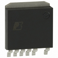
DPA426SN Power Integrations, DPA426SN Datasheet - Page 11

DPA426SN
Manufacturer Part Number
DPA426SN
Description
IC CONV DC-DC DPA SWITCH SPAK
Manufacturer
Power Integrations
Series
DPA-Switch®r
Specifications of DPA426SN
Applications
Converter, Power Over Ethernet and Telecom Applications
Voltage - Input
16 ~ 75 V
Number Of Outputs
1
Voltage - Output
220V
Operating Temperature
-40°C ~ 125°C
Mounting Type
Surface Mount
Package / Case
SPak (5 leads + Tab)
Mounting Style
SMD/SMT
Lead Free Status / RoHS Status
Lead free / RoHS Compliant
Available stocks
Company
Part Number
Manufacturer
Quantity
Price
Company:
Part Number:
DPA426SN
Manufacturer:
POWER
Quantity:
15 000
Part Number:
DPA426SN
Manufacturer:
POWER
Quantity:
20 000
Part Number:
DPA426SN-TL
Manufacturer:
POWER
Quantity:
20 000
Figure 9. Essential Components of the Feedback Circuit. The Schematic Does Not Show ESR of the Output Capacitors (Component
The phase margin is specified at the crossover frequency. It
is the difference between the phase of the loop gain and 180
degrees. A stringent specification will call for a phase margin
of at least 60 degrees under worst case conditions. In no case
should the phase margin be less than 45 degrees. This means the
phase would have to decrease by that amount for the system to
become unstable. Phase margin is also related to the dynamic
characteristics of the system. A low phase margin suggests an
oscillatory response to a load step or other disturbance.
It is also important that the loop gain decrease in magnitude
beyond the crossover frequency. This requirement is generally
specified as gain margin. Gain margin is the difference between
0 dB and the magnitude of the loop gain at the frequency where
the phase is 180 degrees. An acceptable gain margin is greater
than 10 dB. This means the magnitude would have to increase by
that amount for the system to become unstable. Loop gain should
be measured at worst case conditions (generally maximum
input voltage with maximum load) and at the extremes of the
specified ambient temperature, since important component
parameters (especially capacitor ESR) can change greatly with
temperature.
Stabilizing a high frequency forward DC-DC converter presents
some challenges due to the inherently high bandwidth of this
topology. Many DC-DC converter designs use cycle-by-cycle
current-mode control. The DPA-Switch uses classic voltage
Designators are the Same as in the EP-21 Prototype).
D
S
CONTROL
CONTROL
DPA-Switch
U1
C5
C
R4
U2
C6
Input
Return
TL431
U3
R6
L2
R12
C16
C14
mode control to allow operation at duty ratios greater than 50%
without the need for the stabilizing ramp (“slope compensation”)
required with current-mode control. The fundamental system
characteristics of the forward converter in continuous conduction
mode with voltage mode control call for a compensation
circuit with multiple poles and zeros to achieve the desired
loop response.
The crossover frequency for a control loop that uses
DPA-Switch in a forward converter with an optocoupler should
be limited to 10 kHz or less at maximum input voltage and
room temperature. The DPA-Switch has one internal pole at
approximately 30 kHz to filter switching noise. Other poles at
higher frequencies contribute additional phase shift at 30 kHz.
The optocoupler has two poles at approximately 100 kHz. The
phase shift from these poles, combined with the phase shift
introduced by the LC filter at the output of the converter, is
difficult to compensate above 10 kHz.
The objective of the feedback design is to reduce the magnitude
of the loop gain to zero dB at a frequency of 10 kHz or less with
a phase margin near 60 degrees. Although system requirements
and the DPA-Switch fix some quantities that determine loop
characteristics, the designer can manipulate many components
in the feedback circuit to optimize loop stability. Figure 8
shows the essential components of a feedback circuit that uses
an ordinary TL431 regulator to achieve the high loop gain
R9
R10
R11
C10
C11
OUTPUT
RETURN
OUTPUT
+
AN-31
PI-2876-062204
7/04
C
11


