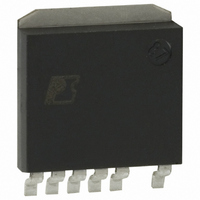
DPA426SN Power Integrations, DPA426SN Datasheet - Page 6

DPA426SN
Manufacturer Part Number
DPA426SN
Description
IC CONV DC-DC DPA SWITCH SPAK
Manufacturer
Power Integrations
Series
DPA-Switch®r
Specifications of DPA426SN
Applications
Converter, Power Over Ethernet and Telecom Applications
Voltage - Input
16 ~ 75 V
Number Of Outputs
1
Voltage - Output
220V
Operating Temperature
-40°C ~ 125°C
Mounting Type
Surface Mount
Package / Case
SPak (5 leads + Tab)
Mounting Style
SMD/SMT
Lead Free Status / RoHS Status
Lead free / RoHS Compliant
Available stocks
Company
Part Number
Manufacturer
Quantity
Price
Company:
Part Number:
DPA426SN
Manufacturer:
POWER
Quantity:
15 000
Part Number:
DPA426SN
Manufacturer:
POWER
Quantity:
20 000
Part Number:
DPA426SN-TL
Manufacturer:
POWER
Quantity:
20 000
Figure 3. Efficiency of the Low Cost EP-21 Prototype with Different
If the transformer has a winding for the bias voltage, be sure
that it has enough turns to maintain a minimum of 8 V bias at
the lowest input voltage. Perform bench verification to confirm
that the converter shuts off at low input voltages by virtue of
the under-voltage lockout circuit, and not because the bias
voltage is too low.
With the actual number of turns on the transformer, verify that
the duty ratio to regulate the output at the minimum input voltage
is less than the minimum DC
The AC flux density contributes to the core losses. For this
reason the AC flux density should be maintained in the range
between 1000 and 1500 gauss (0.1 to 0.15 tesla).
Output Inductor
For a single output application with no bias winding, the
inductor can be a standard off-the-shelf component. Inductors
with multiple windings are typically custom designs.
The inductor value is determined chiefly by the amount of current
ripple that the designer is willing to tolerate. Higher ripple
current will allow an inductor that is smaller both electrically
and physically. The consequence of higher ripple current is the
requirement for more output capacitance with lower equivalent
series resistance (ESR) to meet the specification for output ripple.
Higher current ripple in the inductor also translates to higher
peak current in the DPA-Switch for a given output power. It also
leads to generally greater loss and lower efficiency because the
RMS value of all the currents will be higher.
A convenient design parameter for selection of the inductor is
K
the average current in the inductor. Smaller K
∆I
6
, defined as the ratio of the peak-to-peak ripple current to
C
7/04
AN-31
Devices in the DPA-Switch Family (Synchronous
Rectification Would Improve Efficiency).
90%
88%
86%
84%
82%
80%
35
40
45
DC Input Voltage
50
MAX
55
specified for DPA-Switch.
60
65
DPA424
DPA425
DPA426
∆I
70
corresponds to
75
lower ripple and a larger inductor. Recommended values for
K
trade-off between the size of the inductor, the number and type
of output capacitors, efficiency, and cost. Higher values of K
are not recommended, as these higher ripple currents increase
both the stress and the ripple voltage on the output capacitor.
Whether the inductor is standard off-the-shelf or custom, the
design should minimize the number of turns to reduce the
resistive loss. The construction should also use a low loss core
material.
With user input, the PI Expert design tool computes the
inductance, the RMS current and the peak stored energy to aid in
the selection or specification of the inductor. Peak stored energy
is a useful parameter to select designs that use a closed toroid
core, where magnetic saturation is generally a concern.
Additional Winding for Bias Voltage
If the configuration in Figure 2 (c) is chosen for generation of the
bias voltage, choose the number of turns on the bias winding to
give 12 V at the optocoupler under nominal conditions. Compute
the required number of turns from the lowest regulated output
voltage and the highest forward voltage drops for the output
rectifier and the bias rectifier. Check the bias voltage at minimum
load, maximum line, and add a preload if necessary to maintain
the bias voltage at 8 V minimum. It may also be necessary to
increase the bias winding turns to meet the minimum voltage
requirement with a reasonably small pre-load.
DPA-Switch Selection
The first criterion for the selection of the DPA-Switch is peak
current capability. From the turns ratio of the transformer and
the peak current in the output inductor, estimate the peak current
in the primary of the transformer. The magnetization current of
the transformer should be negligible for this estimate. For lowest
cost, select the smallest DPA-Switch that has a minimum current
limit that is at least 10% greater than the maximum primary
current. The allowance of 10% greater current gives design
margin with the ability to respond to transient loading.
The second criterion for the selection is power dissipation. The
smallest DPA-Switch that will handle the current may dissipate
too much power to meet the efficiency requirements. Even if
efficiency is not a concern, the smallest device may get too hot if
system constraints prevent good thermal design. Multiplication
of the R
gives a reasonable estimate of the power dissipation in the
DPA-Switch. The DPA-Switch dissipates approximately 25%
of the total system loss in designs without synchronous
rectifiers.
∆I
are between 15 and 20 percent. The choice of K
DS(ON)
by the square of the RMS current in the primary
∆I
involves a
∆I


