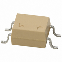
TLP190B(U,C,F) Toshiba, TLP190B(U,C,F) Datasheet - Page 68

TLP190B(U,C,F)
Manufacturer Part Number
TLP190B(U,C,F)
Description
PHOTOVOLTAIC COUPLER 4-MFSOP
Manufacturer
Toshiba
Specifications of TLP190B(U,C,F)
Number Of Channels
1
Input Type
DC
Voltage - Isolation
2500Vrms
Voltage - Output
8V
Current - Output / Channel
20µA
Current - Dc Forward (if)
50mA
Output Type
Photovoltaic
Mounting Type
Surface Mount
Package / Case
6-MFSOP (4 Lead)
Configuration
1 Channel
Maximum Collector Emitter Voltage
3 V
Maximum Forward Diode Voltage
1.7 V
Maximum Reverse Diode Voltage
3 V
Maximum Rise Time
0.2 ms
Maximum Fall Time
1 ms
Maximum Operating Temperature
+ 85 C
Minimum Operating Temperature
- 40 C
Maximum Input Diode Current
50 mA
Output Device
Photovoltaic
Number Of Elements
1
Reverse Breakdown Voltage
3V
Forward Voltage
1.7V
Forward Current
50mA
Collector-emitter Voltage
Not RequiredV
Package Type
MFSOP
Collector Current (dc) (max)
Not RequiredA
Isolation Voltage
2500Vrms
Collector-emitter Saturation Voltage
Not RequiredV
Current Transfer Ratio
Not Required%
Pin Count
4
Mounting
Surface Mount
Operating Temp Range
-25C to 85C
Operating Temperature Classification
Commercial
Lead Free Status / RoHS Status
Lead free / RoHS Compliant
Vce Saturation (max)
-
Current Transfer Ratio (max)
-
Current Transfer Ratio (min)
-
Lead Free Status / Rohs Status
Lead free / RoHS Compliant
Other names
TLP190B
TLP190B
TLP190BF
TLP190B
TLP190BF
11
2
5 V
[ Photo-IC couplers: high-speed base/gate drive applications ]
Driving the Base of a 15-A-Class GTR ( Giant Transistor ) Module
Driving the Base of a 100-A-Class GTR Module
Driving the Gate of a 15-A-Class IGBT ( Insulated Gate Bipolar Transistor ) Module
V
CC
5 V
V
LSTTL
5 V
390 Ω
Inverter and AC-DC Servo Applications
8 mA
TLP109 / TLP2409
TLP550 / TLP559
TLP759
CC
LSTTL
390 Ω
8 mA
Photocoupler Application Circuit Examples
LSTTL
390 Ω
8 mA
TLP557
TLP351 / TLP2541
1
2
3
4
TLP557
Rex 4.3 Ω
Rex 4.3 Ω
GTR Direct Drive
IGBT /
Power MOS Direct Drive
High-Speed
8
7
6
5
(Numerical control, Robotics)
0.1 μF
2 Ω
Base/Gate Drive Circuit
6 V
V
8 V
CC
V
DC Servo
CC
V
V
CC
EE
47 μF
100 μF
150 Ω
M
68
TLP557
(for medium-power IGBTs)
(for small-power IGBTs)
TLP118 / TLP554
The TLP557 drives the base of a GTR directly.
An external resistor, Rex, is connected between
pins 6 and 7. This resistor causes the base current
to become constant and stabilizes the GTR drive.
The TLP557 photo-IC coupler and two booster
transistors can drive a high-power GTR.
The TLP151, TLP351, TLP701, TLP705 and
TLP2541 high-speed photo-IC photocouplers can
drive a low-power IGBT directly.
Base/Gate Drive Circuit
: TLP351 / TLP701 / TLP705
: TLP350/ TLP358/ TLP700
Inverter (PWM)
AC Servo
M


