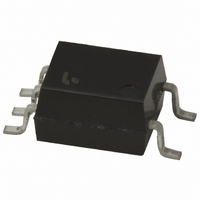
TLP114A(TPR,F) Toshiba, TLP114A(TPR,F) Datasheet - Page 24

TLP114A(TPR,F)
Manufacturer Part Number
TLP114A(TPR,F)
Description
TRANSCOUPLER HS TRANS OUT 5-MSOP
Manufacturer
Toshiba
Specifications of TLP114A(TPR,F)
Number Of Channels
1
Input Type
DC
Voltage - Isolation
3750Vrms
Current Transfer Ratio (min)
20% @ 16mA
Voltage - Output
20V
Current - Output / Channel
8mA
Current - Dc Forward (if)
20mA
Output Type
Transistor with Vcc
Mounting Type
Surface Mount
Package / Case
5-MSOP
Output Device
Transistor With Base
Number Of Elements
1
Reverse Breakdown Voltage
5V
Forward Current
20mA
Package Type
MFSOP
Collector Current (dc) (max)
8mA
Isolation Voltage
3750Vrms
Power Dissipation
100mW
Pin Count
5
Mounting
Surface Mount
Operating Temp Range
-55C to 100C
Operating Temperature Classification
Industrial
Lead Free Status / RoHS Status
Lead free / RoHS Compliant
Vce Saturation (max)
-
Current Transfer Ratio (max)
-
Lead Free Status / Rohs Status
Compliant
4
Photocouplers for IGBT/MOSFET Gate Drive
*Under development. Specifications subject to change without notice. For the latest information, please contact your nearest Toshiba sales representative.
Note 1: The EN60747-5-2 safety standard for compact packages is different from that for standard DIP packages.
Note 2: BSI and IEC: : Approved (supplementary or basic insulation)
TLP151*
TLP151A*
TLP155E
TLP2451
TLP2451A*
TLP350
TLP350F
TLP350H*
TLP350HF*
TLP351
TLP351F
TLP351A*
TLP351AF*
TLP351H*
TLP351HF*
TLP352*
TLP352F*
Part Number
Since the mini-flat package is a compact package, please contact your nearest Toshiba sales representative for more details.
TÜV and VDE: : Approved
For the latest information, please contact your nearest Toshiba sales representative.
Selection Guide
EN 60065- and IEC 60065-approved, EN 60950- and IEC 60950-approved
EN 60747-5-2-approved with option V4 or D4
Pin Configuration
8
1
8
1
8
1
8
1
8
1
8
1
8
1
6
1
6
1
7
2
7
2
7
2
7
2
7
2
7
2
7
2
5
5
6
3
6
3
6
3
: Design which meets safety standard/approval pending as of January 2011
6
3
6
3
6
3
6
3
4
3
4
3
5
4
5
4
5
4
5
4
5
4
5
4
5
4
SO6 (reinforced Insulation)
T
Direct drive of a
small-power
IGBT/MOSFET
SO6 (reinforced Insulation)
T
Direct drive of a
small-power
IGBT/MOSFET
SO8
T
Direct drive of a
small-power
IGBT/MOSFET
High CMR
DIP8
Direct drive of a
medium-power
IGBT/MOSFET
High CMR
Low power dissipation
DIP8
T
Direct drive of a
medium-power
IGBT/MOSFET
High CMR
DIP8
Direct drive of a
small-power
IGBT/MOSFET
Low power dissipation
DIP8
Direct drive of a
medium-power
IGBT/MOSFET
Low power dissipation
T
DIP8
Direct drive of a
medium-power
IGBT/MOSFET
Low power dissipation
DIP8
T
Direct drive of a
small-power
IGBT/MOSFET
High CMR
opr
opr
opr
opr
opr
opr
= 110°C (max)
= 100°C (max)
= 125°C (max)
= 125°C (max)
= 125°C (max)
= 125°C (max)
Features
: Approved (reinforced insulation)
Delay Time (Max)
Propagation
0.7 μs
0.5 μs
0.2 μs
0.7 μs
0.5 μs
0.5 μs
0.5 μs
0.7 μs
0.7 μs
0.7 μs
0.2 μs
24
current (max):
current (max):
current (max):
current (max):
current (max):
current (max):
current (max):
current (max):
current (max):
Peak output
Peak output
Peak output
Peak output
Peak output
Peak output
Peak output
Peak output
Peak output
Output
±0.6 A
±0.6 A
±0.6 A
±2.5 A
±2.5 A
±2.5 A
±0.6 A
±0.6 A
±6.0 A
: Design which meets safety standard/approval pending as of January 2011
5 mA
7.5 mA
5 mA
5 mA
5 mA
(Max)
5 mA
5 mA
5 mA
5 mA
I
FHL
Vrms
Vrms
Vrms
Vrms
Vrms
3750
3750
3750
3750
3750
3750
Vrms
3750
Vrms
3750
Vrms
3750
Vrms
BVs
UL/cUL TÜV
/
/
/
/
/
/
/
/
/
/
/
Safety Standards
VDE
(1)
(1)
BSI
(2)
IEC


