MT9HTF6472AY-667D4 Micron Technology Inc, MT9HTF6472AY-667D4 Datasheet - Page 19

MT9HTF6472AY-667D4
Manufacturer Part Number
MT9HTF6472AY-667D4
Description
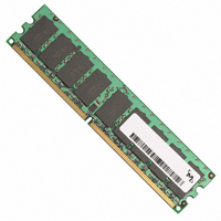
MODULE DDR2 512MB 240-DIMM
Manufacturer
Micron Technology Inc
Datasheet
1.MT9HTF12872AY-40ED1.pdf
(44 pages)
Specifications of MT9HTF6472AY-667D4
Memory Type
DDR2 SDRAM
Memory Size
512MB
Package / Case
240-DIMM
Lead Free Status / RoHS Status
Lead free / RoHS Compliant
Speed
-
Other names
557-1303
MT9HTF6472AY-667D4
MT9HTF6472AY-667D4
Figure 7:
DQS# Enable/Disable
pdf: 09005aef80e6f860, source: 09005aef80e5b799
HTF9C32_64_128x72AG_2.fm - Rev. C 6/05 EN
Extended Mode Register Definition
The DQS# enable function is defined by bit E10. When enabled (bit E10 = 0), DQS# is the
complement of the differential data strobe pair DQS/DQS#. When disabled (bit E10 = 1),
DQS is used in a single-ended mode and the DQS# pin is disabled. This function is also
used to enable/disable RDQS#. If RDQS is enabled (E11 = 1) and DQS# is enabled (E10 =
0), then both DQS# and RDQS# will be enabled. RDQS/RDQS# is supported only on
RDIMMs using x8 DDR2 SDRAM devices.
256MB Address Bus
512MB Address Bus
1GB Address Bus
BA2
E15
16
0
0
0
1
1
BA1
15
BA1
E14
256MB, 512MB, 1GB (x72, SR, ECC) 240-Pin DDR2 SDRAM UDIMM
EMR
15
EMR
0
1
0
1
E12
14
0
1
BA1
14
BA0
14
BA0
EMR
Extended Mode Register (EMRS2)
Extended Mode Register (EMRS3)
E9
Extended Mode Register (EMRS)
0
0
0
1
1
E11
0
1
Disabled
Outputs
Enabled
13
13
0
BA0
A13
13
0
Mode Register Set (MRS)
E8
A13
RDQS Enable
0
0
1
0
1
E10
Disabled
Reserved
out
out
0
1
out
Mode Register Set
12
12
E7
A12 A11
A12 A11
12
0
1
0
0
1
A12 A11
DQS# Enable
RDQS
RDQS
RDQS
Disable
Enable
OCD Operation
OCD Not Supported
Reserved
Reserved
Reserved
OCD default state
11
11
11
DQS#
DQS#
DQS#
10
10
10
A10
A10
A10
OCD Program
OCD Program
OCD Program
9
9
A9
A9
9
A9
E6
0
0
1
1
8
8
A8
A8
8
A8
E2
†
0
1
0
1
7
7
†
7
A7 A6 A5 A4 A3
A7 A6 A5 A4 A3
A7 A6 A5 A4 A3
Rtt (nominal)
R
Rtt Disabled
Rtt
Rtt
TT
† During initialization, all three bits must be set to ‘1’
‡ Available on -667 speed grade parts only.
150Ω
6
6
75Ω
50Ω ‡
6
for OCD Default State, then must be set to ‘0’
before initialization is finished, as detailed in the
initialization procedure.
Posted CAS# R
Posted CAS# Rtt
Posted CAS# Rtt
5
5
5
19
E5
0
0
0
0
1
1
1
1
4
4
4
E4
0
0
1
1
0
0
1
1
3
3
3
E3
0
1
0
1
0
1
0
1
TT
2
2
2
A2 A1 A0
A2 A1 A0
Posted CAS# Additive Latency (AL)
A2 A1 A0
ODS
ODS
ODS
E1
0
1
1
1
1
Micron Technology, Inc., reserves the right to change products or specifications without notice.
DLL
DLL
Full Strength
Reduced Strength
DLL
E0
0
0
0
1
0
Output Drive Strength
Disable (Test/Debug)
Reserved
Reserved
Reserved
Extended Mode
Register (Ex)
Extended Mode
Register (Ex)
Enable (Normal)
Address Bus
Address Bus
Extended Mode
Register (Ex)
Address Bus
0
1
2
3
4
DLL Enable
©2003, 2004, 2005 Micron Technology, Inc. All rights reserved.
DQS# Enable/Disable


