ZUP20-10/U TDK Corporation, ZUP20-10/U Datasheet - Page 39
ZUP20-10/U
Manufacturer Part Number
ZUP20-10/U
Description
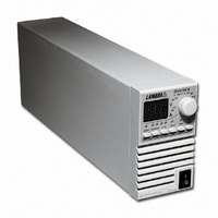
PWR SUP BENCH PROG 0-20V 200W
Manufacturer
TDK Corporation
Series
ZUPr
Type
Programmabler
Specifications of ZUP20-10/U
Load Regulation
0.01%
Voltage - Output
0 ~ 20V
Number Of Outputs
1
Power (watts)
200W
Applications
Commercial
Power Supply Type
Switching (Closed Frame)
Voltage - Input
85 ~ 265VAC
Mounting Type
Chassis Mount
1st Output
0 ~ 20 VDC @ 10A
Size / Dimension
13.78" L x 4.88" W x 2.76" H (350mm x 124mm x 70mm)
Power (watts) - Rated
200W
Operating Temperature
0°C ~ 50°C
Efficiency
78%
Approvals
CE, EN, UL
Line Regulation
0.01%
Power Supply Output Type
Variable
No. Of Outputs
1
Output Voltage
20V
Output Current
10A
Power Rating
200W
Input Voltage
85V AC To 265V AC
Length
350mm
Width
70mm
Accuracy
0.02% + 12 mV
Brand/series
ZUP
Current, Output
10 A
Display Type
Digital Meter
Power, Output
200 W
Power, Rating
200 W (Max.)
Regulation, Line
0.01% + 2 mA⁄1 mV + 0.005%
Regulation, Load
0.01% + 5 mA⁄2 mV + 0.005%
Standards
UL Listed, CE Marked
Temperature Coefficient
30 ppm⁄°C (CV)⁄100 ppm⁄°C (CC)
Temperature, Operating, Maximum
50 °C
Temperature, Operating, Minimum
0 °C
Voltage, Input
85-265 VAC
Voltage, Noise
50 mV @ 20 MHz BW
Voltage, Output
20 VDC
Voltage, Ripple
5 mV @ 5 Hz to 1 MHz
Lead Free Status / RoHS Status
Lead free / RoHS Compliant
3rd Output
-
2nd Output
-
4th Output
-
Lead Free Status / Rohs Status
RoHS Compliant part
Other names
285-1673
Q1142280
ZUP20-10/U
ZUP2010/U
Q1142280
ZUP20-10/U
ZUP2010/U


4.4.13 Auto Parallel Operation
1.Up to five units of the same rating can be connected in an auto-parallel combination to provide up to
2. Foldback protection if desired, may only be used with the master unit. When the master unit shuts
3. Setting the voltage and current:
4.While operating in CV mode, the master unit regulates the output voltage and the slave units operate
5. Over Voltage Protection:
6. Connection to the Load:
parallel units. During operation, the master unit operates at CV mode and the slave units at CC mode.
five times the output current capability. One of the power supplies operates as a master and the
remaining units as slaves. The slave units are analog programmed by the master unit. At remote
operation, only the master unit can be programmed by the computer while the slave units may be
connected to the computer for actual voltage and current readback only.
down it programs the slave units to zero output voltage.
The output voltage of the slave units should be programmed higher than the output and the master to
avoid interference with the master CV control. Output voltage of the master should be programmed
to the desired voltage, and the current limit to the desired load current divided by the number of
as controlled current source, following the master output current. It is recommended to design the
power system so that each unit will supply up to 95% of it’s current rating, because of an imbalance
which may be caused by cabling and connections voltage drop.
OVP of the slave units should be adjusted higher than the Master OVP. When the master unit shuts
down, it programs the slave units to zero output voltage. If a slave unit shuts down (when it’s OVP is
set lower than the master output voltage), only that unit will shut down and remaining slave units
will supply all the load current.
sensing. Refer Fig. 4-9, 4-10 & 4-11 for typical connections of paralleled power supplies. The figure
below shows connection of two units, however the same connection method applies for up to 5 units.
resistance should be as close as possible to achieve current balance between power supplies.
COM
VCVP
VCCP
RCCP
COM
VCVP
VCCP
RCCP
With local sensing it is important to minimize the wire length and resistance. Also the wires
- S
+S
- S
+S
P
P
2
2
14
14
13
13
1
1
On/Off
Output Good
VRFV
VRFI
RCVP
- LS
+LS
Output Good
On/Off
VRFV
VRFI
RCVP
- LS
+LS
At auto-parallel mode, power supplies can be connected in local or remote
The master unit OVP should be adjusted to the desired OVP level. The
MASTER
SUPPLY
POWER
SUPPLY
POWER
SLAVE
NOTE
- V
+V
- V
+V
Fig. 4-9: Auto-parallel with local sensing
(ZUP rear panel view)
+
_
LOAD
Related parts for ZUP20-10/U
Image
Part Number
Description
Manufacturer
Datasheet
Request
R

Part Number:
Description:
PWR SUP BENCH PROG 0-20V 400W
Manufacturer:
TDK Corporation
Datasheet:
Part Number:
Description:
PWR SUP BENCH PROG 0-20V 800W
Manufacturer:
TDK Corporation
Datasheet:

Part Number:
Description:
TDK DC to DC Converters, DC to AC Inverters
Manufacturer:
TDK Corporation
Datasheet:
Part Number:
Description:
TDK DC to DC Converters, DC to AC Inverters
Manufacturer:
TDK Corporation
Datasheet: