MA240017 Microchip Technology, MA240017 Datasheet - Page 140
MA240017
Manufacturer Part Number
MA240017
Description
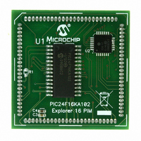
MODULE PLUG-IN PIC24F16KA102 PIM
Manufacturer
Microchip Technology
Series
PIC®r
Specifications of MA240017
Accessory Type
Plug-In Module (PIM) - PIC24F16KA102
Product
Microcontroller Modules
Data Bus Width
16 bit
Core Processor
PIC24F16KA102
Operating Supply Voltage
3 V to 3.6 V
Development Tools By Supplier
Integrated Development Environment, Assembler, ANSI C Compiler
Processor Series
PIC24F
Silicon Manufacturer
Microchip
Core Architecture
PIC
Core Sub-architecture
PIC24
Silicon Core Number
PIC24F
Silicon Family Name
PIC24FxxKAxx
Lead Free Status / RoHS Status
Lead free / RoHS Compliant
For Use With/related Products
Explorer 16 (DM240001 or DM240002)
For Use With
DM240001 - BOARD DEMO PIC24/DSPIC33/PIC32
Lead Free Status / Rohs Status
Lead free / RoHS Compliant
Available stocks
Company
Part Number
Manufacturer
Quantity
Price
Company:

Part Number:
MA240017
Manufacturer:
MICROCHIP
Quantity:
12 000


PIC24F16KA102 FAMILY
REGISTER 17-1:
DS39927B-page 138
bit 15
bit 7
Legend:
R = Readable bit
-n = Value at POR
bit 15
bit 14
bit 13
bit 12
bit 11
bit 10
bit 9
bit 8
bit 7
bit 6
R/W-0
I2CEN
R/W-0
GCEN
I2CEN: I2C1 Enable bit
1 = Enables the I2C1 module and configures the SDA1 and SCL1 pins as serial port pins
0 = Disables the I2C1 module; all I
Unimplemented: Read as ‘0’
I2CSIDL: Stop in Idle Mode bit
1 = Discontinues module operation when device enters an Idle mode
0 = Continues module operation in Idle mode
SCLREL: SCL1 Release Control bit (when operating as I
1 = Releases SCL1 clock
0 = Holds SCL1 clock low (clock stretch)
If STREN = 1:
Bit is R/W (i.e., software may write ‘0’ to initiate stretch and write ‘1’ to release clock). Hardware clear at
beginning of slave transmission. Hardware clear at end of slave reception.
If STREN = 0:
Bit is R/S (i.e., software may only write ‘1’ to release clock). Hardware clear at beginning of slave transmission.
IPMIEN: Intelligent Peripheral Management Interface (IPMI) Enable bit
1 = IPMI Support mode is enabled; all addresses Acknowledged
0 = IPMI Support mode is disabled
A10M: 10-Bit Slave Addressing bit
1 = I2C1ADD is a 10-bit slave address
0 = I2C1ADD is a 7-bit slave address
DISSLW: Disable Slew Rate Control bit
1 = Slew rate control disabled
0 = Slew rate control enabled
SMEN: SMBus Input Levels bit
1 = Enables I/O pin thresholds compliant with the SMBus specification
0 = Disables the SMBus input thresholds
GCEN: General Call Enable bit (when operating as I
1 = Enables interrupt when a general call address is received in the I2C1RSR (module is enabled for
0 = General call address disabled
STREN: SCL1 Clock Stretch Enable bit (when operating as I
Used in conjunction with the SCLREL bit.
1 = Enables software or receive clock stretching
0 = Disables software or receive clock stretching
STREN
R/W-0
reception)
U-0
—
I2C1CON: I2C1 CONTROL REGISTER
HC = Hardware Clearable bit
W = Writable bit
‘1’ = Bit is set
I2CSIDL
ACKDT
R/W-0
R/W-0
R/W-0, HC
R/W-1 HC
SCLREL
ACKEN
2
C™ pins are controlled by port functions
Preliminary
U = Unimplemented bit, read as ‘0’
‘0’ = Bit is cleared
R/W-0, HC
IPMIEN
R/W-0
RCEN
2
C slave)
2
C slave)
2
R/W-0, HC
C slave)
R/W-0
A10M
PEN
© 2009 Microchip Technology Inc.
x = Bit is unknown
R/W-0, HC
DISSLW
R/W-0
RSEN
R/W-0, HC
SMEN
R/W-0
SEN
bit 8
bit 0
Related parts for MA240017
Image
Part Number
Description
Manufacturer
Datasheet
Request
R

Part Number:
Description:
Manufacturer:
Microchip Technology Inc.
Datasheet:
Part Number:
Description:
Manufacturer:
Microchip Technology Inc.
Datasheet:
Part Number:
Description:
Manufacturer:
Microchip Technology Inc.
Datasheet:
Part Number:
Description:
Manufacturer:
Microchip Technology Inc.
Datasheet:
Part Number:
Description:
Manufacturer:
Microchip Technology Inc.
Datasheet:
Part Number:
Description:
Manufacturer:
Microchip Technology Inc.
Datasheet:
Part Number:
Description:
Manufacturer:
Microchip Technology Inc.
Datasheet:
Part Number:
Description:
Manufacturer:
Microchip Technology Inc.
Datasheet: