MA240017 Microchip Technology, MA240017 Datasheet - Page 199
MA240017
Manufacturer Part Number
MA240017
Description
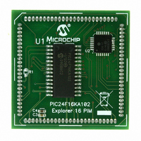
MODULE PLUG-IN PIC24F16KA102 PIM
Manufacturer
Microchip Technology
Series
PIC®r
Specifications of MA240017
Accessory Type
Plug-In Module (PIM) - PIC24F16KA102
Product
Microcontroller Modules
Data Bus Width
16 bit
Core Processor
PIC24F16KA102
Operating Supply Voltage
3 V to 3.6 V
Development Tools By Supplier
Integrated Development Environment, Assembler, ANSI C Compiler
Processor Series
PIC24F
Silicon Manufacturer
Microchip
Core Architecture
PIC
Core Sub-architecture
PIC24
Silicon Core Number
PIC24F
Silicon Family Name
PIC24FxxKAxx
Lead Free Status / RoHS Status
Lead free / RoHS Compliant
For Use With/related Products
Explorer 16 (DM240001 or DM240002)
For Use With
DM240001 - BOARD DEMO PIC24/DSPIC33/PIC32
Lead Free Status / Rohs Status
Lead free / RoHS Compliant
Available stocks
Company
Part Number
Manufacturer
Quantity
Price
Company:

Part Number:
MA240017
Manufacturer:
MICROCHIP
Quantity:
12 000


26.3
In PIC24F16KA102 family devices, in addition to the
WDT module, a DSWDT module is present which runs
while the device is in Deep Sleep, if enabled. It is
driven by either the SOSC or LPRC oscillator. The
clock source is selected by the Configuration bit,
DSWCKSEL (FDS<4>).
The DSWDT can be configured to generate a time-out
at 2.1 ms to 25.7 days by selecting the respective
postscaler. The postscaler can be selected by the
Configuration
When the DSWDT is enabled, the clock source is also
enabled.
DSWDT is one of the sources that can wake-up the
device from Deep Sleep mode.
26.4
For all devices in the PIC24F16KA102 family, code
protection for the boot segment is controlled by the
Configuration bit, BSS0, and the general segment by
the Configuration bit, GSS0. These bits inhibit external
reads and writes to the program memory space; this
has no direct effect in normal execution mode.
Write protection is controlled by bit, BWRP, for the boot
segment and bit, GWRP, for the general segment in the
Configuration Word. When these bits are programmed
to ‘0’, internal write and erase operations to program
memory are blocked.
© 2009 Microchip Technology Inc.
Deep Sleep Watchdog Timer
(DSWDT)
Program Verification and
Code Protection
bits,
DSWDTPS<3:0>
(FDS<3:0>).
Preliminary
PIC24F16KA102 FAMILY
26.5
PIC24F16KA102 family microcontrollers can be
serially programmed while in the end application circuit.
This is simply done with two lines for clock (PGCx) and
data (PGDx) and three other lines for power, ground
and the programming voltage. This allows customers to
manufacture boards with unprogrammed devices and
then program the microcontroller just before shipping
the product. This also allows the most recent firmware
or a custom firmware to be programmed.
26.6
When MPLAB
in-circuit debugging functionality is enabled. This
function allows simple debugging functions when used
with MPLAB IDE. Debugging functionality is controlled
through the EMUCx (Emulation/Debug Clock) and
EMUDx (Emulation/Debug Data) pins.
To use the in-circuit debugger function of the device,
the design must implement ICSP connections to
MCLR,
EMUDx/EMUCx pin pair. In addition, when the feature
is enabled, some of the resources are not available for
general use. These resources include the first 80 bytes
of data RAM and two I/O pins.
In-Circuit Serial Programming
In-Circuit Debugger
V
DD
,
®
ICD 2 is selected as a debugger, the
V
SS
,
PGCx,
PGDx
DS39927B-page 197
and
the
Related parts for MA240017
Image
Part Number
Description
Manufacturer
Datasheet
Request
R

Part Number:
Description:
Manufacturer:
Microchip Technology Inc.
Datasheet:
Part Number:
Description:
Manufacturer:
Microchip Technology Inc.
Datasheet:
Part Number:
Description:
Manufacturer:
Microchip Technology Inc.
Datasheet:
Part Number:
Description:
Manufacturer:
Microchip Technology Inc.
Datasheet:
Part Number:
Description:
Manufacturer:
Microchip Technology Inc.
Datasheet:
Part Number:
Description:
Manufacturer:
Microchip Technology Inc.
Datasheet:
Part Number:
Description:
Manufacturer:
Microchip Technology Inc.
Datasheet:
Part Number:
Description:
Manufacturer:
Microchip Technology Inc.
Datasheet: