DEMOBOARD TLE8201R Infineon Technologies, DEMOBOARD TLE8201R Datasheet - Page 14
DEMOBOARD TLE8201R
Manufacturer Part Number
DEMOBOARD TLE8201R
Description
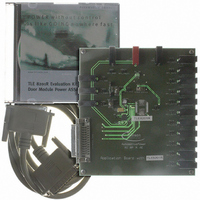
BOARD DEMO TLE8201R V1.0
Manufacturer
Infineon Technologies
Datasheet
1.TLE8201R.pdf
(45 pages)
Specifications of DEMOBOARD TLE8201R
Main Purpose
Power Management, High & Low Side Driver (Internal FET)
Embedded
No
Utilized Ic / Part
TLE8201
Primary Attributes
1 H-Bridge @ 3A, 4 Half Bridges- 2 @ 1A, 2 @ 0.5A, 5 High Side 1@ 2.5A, 4 @ 0..5A
Secondary Attributes
SPI Interface, Intended for Automotive Door
Lead Free Status / RoHS Status
Lead free / RoHS Compliant
Other names
DEMOBOARDTLE8201RIN


4.3
4.3.1
The SPI is used for bidirectional communication with a control unit. The TLE 8201R acts
as SPI-slave and the control unit acts as SPI-master. The 16-bit control word is read via
the DI serial data input. The status word appears synchronously at the DO serial data
output. The communication is synchronized by the serial clock input CLK.
Standard data transfer timing is shown in
falling edge. CLK must be low during CSN transition. The transfer is MSB first.
The transmission cycle begins when the chip is selected with the chip-select-not (CSN)
input (H to L). Then the data is clocked through the shift register. The transmission ends
when the CSN input changes from L to H and the word which has been read into the shift
register becomes the control word. The DO output switches then to tristate status,
thereby releasing the DO bus circuit for other uses. The SPI allows to parallel multiple
SPI devices by using multiple CSN lines. The SPI can also be used with other SPI-
devices in a daisy-chain configuration.
Figure 3
4.3.2
The 16-bit SPI frame is composed of an addressable block, an address-independent
block and a 2-bit address as shown in
The control word transmitted from the master to the TLE 7201R is executed at the end
of the SPI transmission (CSN L -> H) and remains valid until a different control word is
transmitted or a power on reset occurs. At the beginning of the SPI transmission (CSN
Data Sheet Rev. 2.0
CLK
CSN
DO
DI
SPI
General
Register Address
CSN High to Low & rising edge of SCLK: SDO is enabled. Status information is transfered to Output Shift Register
SPI standard data transfer timing
EF
15 14 13 12 11 10
CSN Low to High: Data from Shift-Register is transfered to Output Driver Logic
15
15
14
14
13
13
SDO: State will change on the rising edge of CLK-Signal
SDI: Data will be accepted on the falling edge of CLK-Signal
12
12
11
11
10
10
9
9
9
previous Status
actual Data
8
8
8
Figure
7
7
7
14
Figure
6
6
6
4.
5
5
5
4
4
4
3. The clock polarity is data valid on
3
3
3
2
2
2
1
1
1
0
0
0
actual Status
15
15
new Data
15 14
14
TLE 8201R
14
2006-06-07
time
Related parts for DEMOBOARD TLE8201R
Image
Part Number
Description
Manufacturer
Datasheet
Request
R

Part Number:
Description:
BOARD DEMO FOR TLE6208-3G
Manufacturer:
Infineon Technologies
Datasheet:

Part Number:
Description:
BOARD DEMO FOR TLE6208-6G
Manufacturer:
Infineon Technologies
Datasheet:

Part Number:
Description:
BOARD DEMO FOR TLE 6288R
Manufacturer:
Infineon Technologies
Datasheet:

Part Number:
Description:
BOARD DEMO FOR TLE 6214L
Manufacturer:
Infineon Technologies
Datasheet:

Part Number:
Description:
BOARD DEMO FOR TLE 7209-2R
Manufacturer:
Infineon Technologies
Datasheet:

Part Number:
Description:
BOARD DEMO PROFET V2.0BTS
Manufacturer:
Infineon Technologies
Datasheet:

Part Number:
Description:
BOARD DEMO FOR TLE 6244X
Manufacturer:
Infineon Technologies
Datasheet:

Part Number:
Description:
BOARD DEMO FOR TLE 6365 REV.4
Manufacturer:
Infineon Technologies
Datasheet:

Part Number:
Description:
BOARD DEMO FOR TLE 6389-2GV
Manufacturer:
Infineon Technologies
Datasheet:

Part Number:
Description:
BOARD DEMO FOR TLE 6389-2 GV50
Manufacturer:
Infineon Technologies
Datasheet:

Part Number:
Description:
Manufacturer:
Infineon Technologies AG
Datasheet:
Part Number:
Description:
Manufacturer:
Infineon Technologies AG
Datasheet:
Part Number:
Description:
Manufacturer:
Infineon Technologies AG
Datasheet:
Part Number:
Description:
Manufacturer:
Infineon Technologies AG
Datasheet:
Part Number:
Description:
Manufacturer:
Infineon Technologies AG
Datasheet: