DEMOBOARD TLE8201R Infineon Technologies, DEMOBOARD TLE8201R Datasheet - Page 21
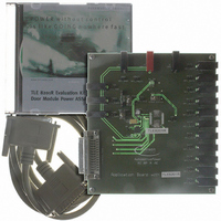
DEMOBOARD TLE8201R
Manufacturer Part Number
DEMOBOARD TLE8201R
Description
BOARD DEMO TLE8201R V1.0
Manufacturer
Infineon Technologies
Datasheet
1.TLE8201R.pdf
(45 pages)
Specifications of DEMOBOARD TLE8201R
Main Purpose
Power Management, High & Low Side Driver (Internal FET)
Embedded
No
Utilized Ic / Part
TLE8201
Primary Attributes
1 H-Bridge @ 3A, 4 Half Bridges- 2 @ 1A, 2 @ 0.5A, 5 High Side 1@ 2.5A, 4 @ 0..5A
Secondary Attributes
SPI Interface, Intended for Automotive Door
Lead Free Status / RoHS Status
Lead free / RoHS Compliant
Other names
DEMOBOARDTLE8201RIN


4.3.4.1
In addition to the 16 bits transferred from the TLE 7201R to the SPI master, an additional
Error Flag (EF) is transmitted at the DO pin. The EF status is shown on the DO pin after
CSN H->L, before the first rising edge at CLK, as shown in
The Error flag is set to H if any of the Status Registers contains an error message (i.e.
EF = EF_00 or EF_01 or EF_10 or EF_11)
.
Figure 6
4.3.5
Electrical Characteristics - SPI-timing
8 V <
-40 C <
Pos. Parameter
4.3.1 CSN lead time
4.3.2 CSN lag time
4.3.3 Fall time for CSN, CLK, DI,
4.3.4 Rise time for CSN, CLK,
Data Sheet Rev. 2.0
V
DO
DI, DO
S
T
< 20 V; 4.75 V <
j
Error-Flag
Electrical Characteristics
< 150 C; unless otherwise specified
Error Flag transmission on DO during standard SPI transmission
(top), or without additional SPI transmission, CLK low (bottom)
CSN
CLK
CSN
CLK
DO
DO
Z
Z
V
CC
EF
< 5.25 V; INH = High; all outputs open;
Sym-
bol
t
t
t
t
lead
lag
f
r
bit15
EF
21
bit14
min. typ.
100
100
–
–
Limit Values
bit13
–
–
–
–
Z
bit12
max.
–
–
25
25
Figure
Unit Conditions
ns
ns
ns
ns
6.
1
2
3
4
1)
1)
1)
1)
TLE 8201R
2006-06-07
Related parts for DEMOBOARD TLE8201R
Image
Part Number
Description
Manufacturer
Datasheet
Request
R

Part Number:
Description:
BOARD DEMO FOR TLE6208-3G
Manufacturer:
Infineon Technologies
Datasheet:

Part Number:
Description:
BOARD DEMO FOR TLE6208-6G
Manufacturer:
Infineon Technologies
Datasheet:

Part Number:
Description:
BOARD DEMO FOR TLE 6288R
Manufacturer:
Infineon Technologies
Datasheet:

Part Number:
Description:
BOARD DEMO FOR TLE 6214L
Manufacturer:
Infineon Technologies
Datasheet:

Part Number:
Description:
BOARD DEMO FOR TLE 7209-2R
Manufacturer:
Infineon Technologies
Datasheet:

Part Number:
Description:
BOARD DEMO PROFET V2.0BTS
Manufacturer:
Infineon Technologies
Datasheet:

Part Number:
Description:
BOARD DEMO FOR TLE 6244X
Manufacturer:
Infineon Technologies
Datasheet:

Part Number:
Description:
BOARD DEMO FOR TLE 6365 REV.4
Manufacturer:
Infineon Technologies
Datasheet:

Part Number:
Description:
BOARD DEMO FOR TLE 6389-2GV
Manufacturer:
Infineon Technologies
Datasheet:

Part Number:
Description:
BOARD DEMO FOR TLE 6389-2 GV50
Manufacturer:
Infineon Technologies
Datasheet:

Part Number:
Description:
Manufacturer:
Infineon Technologies AG
Datasheet:
Part Number:
Description:
Manufacturer:
Infineon Technologies AG
Datasheet:
Part Number:
Description:
Manufacturer:
Infineon Technologies AG
Datasheet:
Part Number:
Description:
Manufacturer:
Infineon Technologies AG
Datasheet:
Part Number:
Description:
Manufacturer:
Infineon Technologies AG
Datasheet: