DEMOBOARD TLE 6288R Infineon Technologies, DEMOBOARD TLE 6288R Datasheet - Page 17
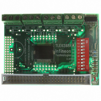
DEMOBOARD TLE 6288R
Manufacturer Part Number
DEMOBOARD TLE 6288R
Description
BOARD DEMO FOR TLE 6288R
Manufacturer
Infineon Technologies
Datasheet
1.TLE6288R.pdf
(32 pages)
Specifications of DEMOBOARD TLE 6288R
Main Purpose
Power Management, High & Low Side Driver (Internal FET)
Embedded
No
Utilized Ic / Part
TLE6288
Primary Attributes
3 Channel High Side, 3 Channel High/Low Side Configurable
Secondary Attributes
SPI Interface
Lead Free Status / RoHS Status
Lead free / RoHS Compliant
Other names
DEMOBOARDTLE6288RIN


Electrical Characteristics: SPI Timing (cont’d)
V
ground, positive current flowing into pin (unless otherwise specified)
Pos.
5.2.10
5.2.11
1) Not subject to production test, specified by design.
2) To get the correct diagnostic information, the transfer delay time has to be extended to the maximum fault filter time
5.3
As soon as a fault occurs for longer than the fault filter time, the fault information is latched into the diagnosis
register (and the Fault pin will change from high to low state). A new error on the same channel will overwrite the
old error report. Serial data out pin (SO) is in a high impedance state when CS is high. If CS receives a LOW signal,
all diagnosis bits can be shifted out serially. If the sent command was valid (see Note in
edge of CS will reset the diagnosis registers (except the channel OT flag) and restart the fault filter time. In case
of an invalid command the device will ignore the data bits and the diagnosis register will not be reset at the rising
CS edge.
Figure 9
For Full Diagnosis there are two diagnostic bits per channel configured as shown in
Diagnosis bit 0 and bit 1 are always set to 1.
Data Sheet
CC
t
f(fault)max
= 4.5 V to 5.5 V,
Parameter
Transfer Delay Time
(CS high time between two
accesses)
Data Valid Time
C
C
L
L
= 200 µs.
= 50 pF to 100 pF
= 220 pF
Diagnostic Serial Data Out SO
SPI Diagnostics
Two Bits per Channel Diagnostic Feedback plus two Overtemperature Flags
MSB
15
Ch.6
HH
HL
LH
LL
14
T
j
= -40 °C to +150 °C,
13
1)
Ch.5
2)
12
Normal function
Overload, Shorted Load or Overtemperature
Open Load
Switch Bypassed
11
Ch.4
10
Symbol
t
t
dt
valid
V
9
Ch.3
B
= 6 V to 16 V, Reset = H,
Channel Overtem-
perature Flag
8
Min.
200
–
–
17
Ch.2
7
Limit Values
Typ.
–
–
–
6
Ch.1
5
Bit0 and Bit1
is always 1
Max.
–
120
150
4
V
DO
3
=
Unit Pin/
ns
ns
2
V
CC
Figure
, all voltages with respect to
IC Overtem-
perature Flag
Comment
–
–
1
LSB
Chapter
0
Rev. 2.4, 2007-08-08
9.
Conditions
–
–
5.5) the rising
TLE6288R
SPI
Related parts for DEMOBOARD TLE 6288R
Image
Part Number
Description
Manufacturer
Datasheet
Request
R

Part Number:
Description:
BOARD DEMO FOR TLE6208-3G
Manufacturer:
Infineon Technologies
Datasheet:

Part Number:
Description:
BOARD DEMO TLE8201R V1.0
Manufacturer:
Infineon Technologies
Datasheet:

Part Number:
Description:
BOARD DEMO FOR TLE6208-6G
Manufacturer:
Infineon Technologies
Datasheet:

Part Number:
Description:
BOARD DEMO FOR TLE 6214L
Manufacturer:
Infineon Technologies
Datasheet:

Part Number:
Description:
BOARD DEMO FOR TLE 7209-2R
Manufacturer:
Infineon Technologies
Datasheet:

Part Number:
Description:
BOARD DEMO PROFET V2.0BTS
Manufacturer:
Infineon Technologies
Datasheet:

Part Number:
Description:
BOARD DEMO FOR TLE 6244X
Manufacturer:
Infineon Technologies
Datasheet:

Part Number:
Description:
BOARD DEMO FOR TLE 6365 REV.4
Manufacturer:
Infineon Technologies
Datasheet:

Part Number:
Description:
BOARD DEMO FOR TLE 6389-2GV
Manufacturer:
Infineon Technologies
Datasheet:

Part Number:
Description:
BOARD DEMO FOR TLE 6389-2 GV50
Manufacturer:
Infineon Technologies
Datasheet:

Part Number:
Description:
Manufacturer:
Infineon Technologies AG
Datasheet:
Part Number:
Description:
Manufacturer:
Infineon Technologies AG
Datasheet:
Part Number:
Description:
Manufacturer:
Infineon Technologies AG
Datasheet:
Part Number:
Description:
Manufacturer:
Infineon Technologies AG
Datasheet:
Part Number:
Description:
Manufacturer:
Infineon Technologies AG
Datasheet: