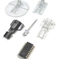
ADNK-5033-FS27 Avago Technologies US Inc., ADNK-5033-FS27 Datasheet - Page 10

ADNK-5033-FS27
Manufacturer Part Number
ADNK-5033-FS27
Description
KIT REF DES OPT MOUSE ADNS-5030
Manufacturer
Avago Technologies US Inc.
Datasheets
1.ADNK-5033-FS27.pdf
(24 pages)
2.ADNK-5033-FS27.pdf
(6 pages)
3.ADNK-5033-FS27.pdf
(32 pages)
Specifications of ADNK-5033-FS27
Main Purpose
Reference Design, Optical Mouse
Utilized Ic / Part
ADNS-5030
Wireless Frequency
27 MHz
Interface Type
USB
Modulation
FSK
For Use With/related Products
MC68HC908QY4A, MC68HC908JB12
Lead Free Status / RoHS Status
Lead free / RoHS Compliant
Secondary Attributes
-
Embedded
-
Primary Attributes
-
Lead Free Status / Rohs Status
Lead free / RoHS Compliant
10
RF Packet Structure
All the mouse data is transmitted by RF front end with
the FSK modulation.
There are two types of RF packet: XY movement packet
or Buttons status/Z movement packet. The Button
status/Z movement packet will also be used for mouse
ID updating process. It will be further described in later
session.
All these packets have the same structure. Each packet
will consist of start field, data field and checksum field.
XY Displacement Packet:
Start Field: Consist of preamble and synchronization
pattern. A header pattern is also included for distinction
between XY movement and button status/Z movement
packet.
Data Field: There are two bytes data in Data field. The
first and second bytes are 8-bit X and Y displacement
respectively. They are presented in 2’s complement
format.
Checksum Field: The 8 bit in Checksum field contains
the sum of the X, Y displacement and the stored ID of
the mouse.
There is one STOP bit after each byte of Data or
Checksum field. Lowest Significant Bit (LSB) will be
transmitted first. The contents of these fields are
encoded by using Manchester Method.
Bit 7
START FIELD
Start
Bit 6
1T period is equal to 104 us Timer interrupt period
SYNC PATTERN AND PREAMBLE
X Displacement
Bit 5
XY displacement or Checksum byte
(12T PERIOD)
Bit 4
DATA FIELD
Bit 3
Y Displacement
Bit 2
Bit 1
(6T PERIOD)
Bit 0
HEADER
CHECKSUM FIELD
Checksum
STOP
Button Status and Z Displacement Packet:
Start Field: Consists of preamble and synchronization
pattern. The header pattern is for distinction between
XY movement and button status/Z movement packet
as mentioned before.
Data Field: The first byte contains the status of the
four buttons. The second byte is either Z movement
value or a new ID value.
In the button status byte, a “1” means the
corresponding button is pressed and “0” means the
button has been released. When the “ID” button status
is “1”, the value of the second byte will represents a
new 8 bit ID to be used by the mouse and receiver
pair. Otherwise, it is an normal Button status/Z
displacement packet where the second byte represent
the Z movement in 2’s complement format.
Checksum Field: The 8 bit in Checksum Field contains
the sum of the X, Y displacement and the stored ID
value.
Again, there is one STOP bit after each byte of Data or
Checksum field. Lowest Significant Bit (LSB) will be
transmitted first. The contents of these fields are
encoded by using Manchester Method.
Bit 7
START FIELD
R
Start
Bit 6
R
1T period is equal to 104 us Timer interrupt period
SYNC PATTERN AND PREAMBLE
Button Status
N-BTN
Bit 5
(12T PERIOD)
Checksum Byte
R-BTN
Button Status Byte
Bit 4
DATA FIELD
L-BTN
Bit 3
Z or ID
Bit 2
ID
Bit 1
R
(6T PERIOD)
Bit 0
HEADER
CHECKSUM FIELD
Checksum
R
STOP
STOP


