ADNK-5033-FS27 Avago Technologies US Inc., ADNK-5033-FS27 Datasheet - Page 8

ADNK-5033-FS27
Manufacturer Part Number
ADNK-5033-FS27
Description
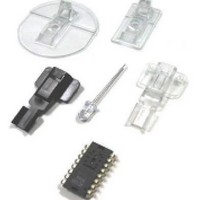
KIT REF DES OPT MOUSE ADNS-5030
Manufacturer
Avago Technologies US Inc.
Datasheets
1.ADNK-5033-FS27.pdf
(24 pages)
2.ADNK-5033-FS27.pdf
(6 pages)
3.ADNK-5033-FS27.pdf
(32 pages)
Specifications of ADNK-5033-FS27
Main Purpose
Reference Design, Optical Mouse
Utilized Ic / Part
ADNS-5030
Wireless Frequency
27 MHz
Interface Type
USB
Modulation
FSK
For Use With/related Products
MC68HC908QY4A, MC68HC908JB12
Lead Free Status / RoHS Status
Lead free / RoHS Compliant
Secondary Attributes
-
Embedded
-
Primary Attributes
-
Lead Free Status / Rohs Status
Lead free / RoHS Compliant
Firmware Implementation
The MC68HC908QY4A mouse firmware is compiled
under CodeWarrior environment from Freescale
Semiconductor Inc. The firmware includes the following
files:
QY4 _OPTICAL_MOUSE.ASM
Main program, includes power up entry point, constant
and variables definition.
QY4_INT.ASM
Timer interrupt service routines RF packet transmit,
timer tick generation.
SENSOR.ASM
ADNS-5030 optical sensor initialization, SPI routine for
optical sensor register read/write operation.
QY4_MOTION.ASM
X-Y motion handler and button detection.
QY4_EEFLASH.ASM
Flash erase/write routines for mouse ID update.
QY4_MISC.ASM
System initialization and miscellaneous routines.
QTQ_REGISTERS.INC
QY4A register header file.
QY4_OPTICAL_MOUSE.H
System header file.
A5030_SENSOR.H
Header file for ADNS-5030 optical sensor.
8
Mouse Firmware Structure
The mouse firmware consists of two main parts; main
routine and timer interrupt routine. A power
management scheme is included to minimize the
power consumption while maximize the performance.
The main program continually checks with the registers
of the optical sensor to see if any XY movement
happened. If any XY movement is detected, it gets the
X and Y displacements from the sensor registers, puts
them in the FIFO buffer and sets the corresponding
flags. For every ms timer tick, it checks the Z movement
and the button status. Timer interrupt is set for every
104 us which is the base time for the 4.8 kHz data rate
transmission. By configuring the timer to Output
Compare mode, the RF_Data output pin can be set,
clear or toggled for every 104 us. The timer interrupt
routine determines whether to set or clear RF_Data
pin at the next interrupt time. It also, determines what
the current RF_Off pin status should be.
Figure 7. Mouse Firmware Structure
GET XY DISPLACEMENT
POWER MANAGEMENT
GET Z DISPLACEMENT
EVERY MILLISECOND
CHECK BUTTON FOR
MAIN PROGRAM
FROM SENSOR
MILLISECOND
FOR EVERY
POWER OFF RF CIRCUIT
TRANSMIT DATA
TRANSMITTED
INTERRUPT
IF ALL DATA
TICK FLAGS
SET TIMER
RETURN
TIMER
IF ANY


