NCP370GEVB ON Semiconductor, NCP370GEVB Datasheet - Page 4
NCP370GEVB
Manufacturer Part Number
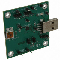
NCP370GEVB
Description
EVAL BOARD FOR NCP370G
Manufacturer
ON Semiconductor
Specifications of NCP370GEVB
Design Resources
NCP370GEVB BOM NCP370GEVB Gerber Files NCP370GEVB Schematic
Main Purpose
Overvoltage Protection
Embedded
No
Utilized Ic / Part
NCP370
Primary Attributes
Overvoltage Protected up to 28V and down to -28V
Secondary Attributes
Reverse Mode
Lead Free Status / RoHS Status
Lead free / RoHS Compliant
For Use With/related Products
NCP370G
Other names
NCP370GEVBOS


ELECTRICAL CHARACTERISTICS
values are at T
Input Voltage Range
Input Voltage
Output Voltage Range
Undervoltage Lockout Threshold
Undervoltage Lockout Hysteresis
Over voltage Lockout Threshold
NCP370MUAITXG
Overvoltage Lockout Hysteresis
Over System Voltage Lockout
Overvoltage Lockout Hysteresis
V
V
Input Standby Current
Input Supply Quiescent Current
Output Standby Current
Reverse Mode current
Minimum DC Current
Overcurrent Threshold
Overcurrent Response
FLAG Output Low Voltage
FLAG Leakage Current
DIR Voltage High
DIR Voltage Low
DIR Leakage Current
REV Voltage High
REV Voltage Low
REV Leakage Current
Thermal Shutdown Temperature
Thermal Shutdown Hysteresis
out
in
to V
to V
out
Characteristics
in
Resistance
Resistance
A
= +25°C)
OVLO
Idd
UVLO
OVLO
Symbols
FLAG
T
OVLO
REV
R
R
DIR
Idd
Idd
V
Vin
UVLO
OVLO
Vol
V
V
SDHYST
V
Idd
I
I
(V
DS(on)
DS(on)
STDOUT
I
V
T
CHG
I
ihREV
REV
OCP
ihDIR
ilREV
V
ilDIR
acc
out
SD
STD
REV
in
in
min
flag
leak
00hyst
IN
leak
leak
hyst
hyst
= 5 V, Minimum/Maximum limits at −40°C < T
00
Disable, Direct and Enhance Modes, V
V
Disable, Direct and Enhance Modes, V
V
V
in
V
V
in
out
No Accessory, V
in
in
falls below to OVLO
Accessory, V
Direct Accessory Short, Reverse Mode,
= 5 V, Direct Mode, Load Connected to V
http://onsemi.com
Rin = 10 kW, V
No Load. Disable Mode, V
(Disable, Direct and Enhance Modes)
rises above UVLO Threshold + UVLO
rises above OVLO
= 4.2 V, Load on V
V
V
I
V
reverse
V
out
out
in
in
Load Connected to V
Vin falls below UVLO Threshold
V
Output Load, V
> OVLO, Sink 1 mA on FLAG Pin
in
falls below to OVLO − OVLO
= 5 V, Reverse Mode, Accessory
= 5 V, Reverse Mode, Accessory
(Disable and Direct Modes)
V
V
Connected to V
rises above OVLO threshold
Sink 50 mA on FLAG Pin
V
V
in
in
> I
No Load. Direct Mode
V
V
out
in
FLAG Level = 5.5 V
1.2 V < V
4
and V
and V
in
in
lim
Connected to V
= 5 V, Direct Mode,
Reverse Mode
= 0 W, 1 A/1 ms
= 4.2 V, I
Mode @ 25°C
out
or V
or V
, Sink 1 mA on FLAG Pin
Conditions
out
out
= 5.5 V, Reverse Modes
out
out
out
out
= 5.5 V, Disable Mode
= 4.2 V, Reverse Mode
00
00
in
in
in
disconnected
disconnected
connected
connected
, Reverse Mode, R
= 5.5 V, Direct
lim
< UVLO
Threshold Enhanced
− OVLO
in
@ 25°C
= 1.6 A
out
in
in
@ 25°C
connected
00hyst
A
out
hyst
< +85°C unless otherwise noted. Typical
out
@ 25°C
= 4.25V
= 0 V
hyst
ILIM
out
1.35
Min
−28
−24
2.5
2.6
6.3
7.9
1.3
1.3
1.2
1.2
45
60
80
8.27
0.02
1.75
Typ
100
130
130
130
130
140
200
200
200
200
150
2.7
6.6
7.0
1.0
1.0
1.0
60
80
30
30
Max
2.10
0.55
0.55
100
145
220
200
220
200
200
280
315
400
400
400
5.5
2.8
6.9
8.6
1.0
28
75
Unit
mW
mW
mV
mV
mV
mV
mA
mA
mA
mA
nA
nA
nA
°C
°C
%
V
V
V
V
V
V
A
A
V
V
V
V
Related parts for NCP370GEVB
Image
Part Number
Description
Manufacturer
Datasheet
Request
R

Part Number:
Description:
Positive and Negative Overvoltage Protection
Manufacturer:
ON Semiconductor
Datasheet:
Part Number:
Description:
ON Semiconductor [VOLTAGE REGULATOR]
Manufacturer:
ON Semiconductor
Datasheet:
Part Number:
Description:
357-036-542-201 CARDEDGE 36POS DL .156 BLK LOPRO
Manufacturer:
ON Semiconductor
Datasheet:
Part Number:
Description:
357-036-542-201 CARDEDGE 36POS DL .156 BLK LOPRO
Manufacturer:
ON Semiconductor
Datasheet:
Part Number:
Description:
357-036-542-201 CARDEDGE 36POS DL .156 BLK LOPRO
Manufacturer:
ON Semiconductor
Datasheet:
Part Number:
Description:
357-036-542-201 CARDEDGE 36POS DL .156 BLK LOPRO
Manufacturer:
ON Semiconductor
Datasheet:
Part Number:
Description:
357-036-542-201 CARDEDGE 36POS DL .156 BLK LOPRO
Manufacturer:
ON Semiconductor
Datasheet:
Part Number:
Description:
357-036-542-201 CARDEDGE 36POS DL .156 BLK LOPRO
Manufacturer:
ON Semiconductor
Datasheet:
Part Number:
Description:
357-036-542-201 CARDEDGE 36POS DL .156 BLK LOPRO
Manufacturer:
ON Semiconductor
Datasheet:
Part Number:
Description:
357-036-542-201 CARDEDGE 36POS DL .156 BLK LOPRO
Manufacturer:
ON Semiconductor
Datasheet:
Part Number:
Description:
357-036-542-201 CARDEDGE 36POS DL .156 BLK LOPRO
Manufacturer:
ON Semiconductor
Datasheet:
Part Number:
Description:
357-036-542-201 CARDEDGE 36POS DL .156 BLK LOPRO
Manufacturer:
ON Semiconductor
Datasheet:
Part Number:
Description:
Manufacturer:
ON Semiconductor
Datasheet:
Part Number:
Description:
Manufacturer:
ON Semiconductor
Datasheet: