NCP370GEVB ON Semiconductor, NCP370GEVB Datasheet - Page 5
NCP370GEVB
Manufacturer Part Number
NCP370GEVB
Description
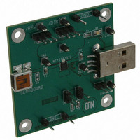
EVAL BOARD FOR NCP370G
Manufacturer
ON Semiconductor
Specifications of NCP370GEVB
Design Resources
NCP370GEVB BOM NCP370GEVB Gerber Files NCP370GEVB Schematic
Main Purpose
Overvoltage Protection
Embedded
No
Utilized Ic / Part
NCP370
Primary Attributes
Overvoltage Protected up to 28V and down to -28V
Secondary Attributes
Reverse Mode
Lead Free Status / RoHS Status
Lead free / RoHS Compliant
For Use With/related Products
NCP370G
Other names
NCP370GEVBOS


NOTE:
Operation
and negative voltages, up to 28 V or down to −28 V on
IN pins. At powerup, with DIR pin = low, REV = high, the
output rises 30 ms after the input rises above the UVLO. The
NCP370 provides a FLAG output, which alerts the system
that a fault has occurred. The FLAG signal rises 30 ms after
the output signal rises.
connected on IN pins and the internal battery is applied on
the OUT pin, allowing the accessory to be powered. In this
mode, no supply must be connected on IN pins and REV pin
must be tied to low level. The NCP370 provides overcurrent
protection for the battery from current faults in the
accessory.
Undervoltage Lockout (UVLO)
adapter charging) under any conditions, the device has a
built−in undervoltage lock out (UVLO) circuit. During
positive going slope on V
from input until V
output will be low as long as V
threshold. This circuit has a 60 mV hysteresis to provide
noise immunity to transient conditions.
UVLO and OVLO comparators are inactivated.
TIMINGS
DIRECT MODE
REVERSE MODE
Start Up Delay
FLAG Going Up Delay
Turn Off Delay
Alert Delay
Disable Time
Reverse Start Up Delay
Reverse FLAG Going Up Delay
Rearming Reverse Delay
Over Current Regulation Time
OCP Delay Time
Reverse Disable Time
The NCP370 provides overvoltage protection for positive
A Reverse Mode is available when an accessory is
To ensure proper turn−on operation from AC/DC (or Wall
In Reverse Mode (REV pin v 0.55 V, DIR w 1.2 V),
Characteristics
Electrical parameters are guaranteed by correlation across the full range of temperature.
in
voltage is above UVLO. The FLAG
in
, the output remains disconnected
in
Symbols
has not reached UVLO
tstart
t
ton
TYPICAL OPERATING CHARACTERISTICS
REVDIS
t
t
t
t
t
RRD
REG
OCP
start
stop
t
t
t
dis
on
off
REV
REV
From V
3 and 9 V
From V
REV = 1.2 V, From DIR = 0.4 V to 1.2 V to V
From REV = 0.55 V to 1.2 V, to V
V
http://onsemi.com
V
V
out
V
in
out
From V
out
From V
From V
in
in
Increasing from 5 V to 8 V at 3 V/ms
w 2.5 V, From REV = 1.2 to 0.55 to
w 0.3 V FLAG = 1.2 V, Reverse Mode
> 2.5 V, R
> OVLO to FLAG v 0.4 V See Figure
> 2.6, V
in
V
From I
in
Increasing from 5 V to 8 V at 3 V/ms
w 0.3 V, Reverse Mode
out
5
in
in
> OVLO to V
> UVLO to V
reverse
> 0.3 V to FLAG = 1.2 V
in
Conditions
Overvoltage Lockout (OVLO)
overvoltage, the device has a built−in overvoltage lock out
(OVLO) circuit. During overvoltage condition, the output is
disabled as long as the input voltage exceeds OVLO.
(Please contact your ON Semiconductor representative for
availability).
This circuit has a 80 mV hysteresis to provide noise
immunity to transient
Oversystem Voltage Lockout (OVLO
supplying the sytem (output) by the Wall Adaptor (input) by
setting DIR = low and REV = low. The R
higher during this mode allowing to handle few 10 mA
voltage (OVLO = 8.27 V typical) on the NCP370 during test
production sequence (I.E: One Time Programming of the
cell phone, PDA). This parameter is 25°C guaranteed only.
FLAG Output
fault has occurred. As soon as a fault state is detected by the
NCP370 (see Figure 3), the FLAG pin output goes low,
alerting the micro−controller to take appropriate action.
V
in
> 0.3 V, Reverse Mode
v 0.3 V
out
To protect connected systems on Vout pin from
Additional OVLO thresholds can be manufactured
FLAG output will be low since V
A second overvoltage comparator is available for
This additional comparator allows to put higher input
The NCP370 provides a FLAG output which alerts that a
= 1 W, Reverse Mode
= 5 V
> I
lim
, 1 A/1 ms
out
out
w 0.3 V
v 0.3 V
in
< 0.3 V.
conditions.
out
Min
0.6
0.6
0.5
20
20
20
in
is higher than OVLO.
200
Typ
1.5
1.5
2.5
1.2
1.2
1.2
30
30
30
00
5
)
DS(on)
Max
5.0
1.8
1.8
1.8
40
40
40
will be
Unit
ms
ms
ms
ms
ms
ms
ms
ms
ms
ms
ms
.
Related parts for NCP370GEVB
Image
Part Number
Description
Manufacturer
Datasheet
Request
R

Part Number:
Description:
Positive and Negative Overvoltage Protection
Manufacturer:
ON Semiconductor
Datasheet:
Part Number:
Description:
ON Semiconductor [VOLTAGE REGULATOR]
Manufacturer:
ON Semiconductor
Datasheet:
Part Number:
Description:
357-036-542-201 CARDEDGE 36POS DL .156 BLK LOPRO
Manufacturer:
ON Semiconductor
Datasheet:
Part Number:
Description:
357-036-542-201 CARDEDGE 36POS DL .156 BLK LOPRO
Manufacturer:
ON Semiconductor
Datasheet:
Part Number:
Description:
357-036-542-201 CARDEDGE 36POS DL .156 BLK LOPRO
Manufacturer:
ON Semiconductor
Datasheet:
Part Number:
Description:
357-036-542-201 CARDEDGE 36POS DL .156 BLK LOPRO
Manufacturer:
ON Semiconductor
Datasheet:
Part Number:
Description:
357-036-542-201 CARDEDGE 36POS DL .156 BLK LOPRO
Manufacturer:
ON Semiconductor
Datasheet:
Part Number:
Description:
357-036-542-201 CARDEDGE 36POS DL .156 BLK LOPRO
Manufacturer:
ON Semiconductor
Datasheet:
Part Number:
Description:
357-036-542-201 CARDEDGE 36POS DL .156 BLK LOPRO
Manufacturer:
ON Semiconductor
Datasheet:
Part Number:
Description:
357-036-542-201 CARDEDGE 36POS DL .156 BLK LOPRO
Manufacturer:
ON Semiconductor
Datasheet:
Part Number:
Description:
357-036-542-201 CARDEDGE 36POS DL .156 BLK LOPRO
Manufacturer:
ON Semiconductor
Datasheet:
Part Number:
Description:
357-036-542-201 CARDEDGE 36POS DL .156 BLK LOPRO
Manufacturer:
ON Semiconductor
Datasheet:
Part Number:
Description:
Manufacturer:
ON Semiconductor
Datasheet:
Part Number:
Description:
Manufacturer:
ON Semiconductor
Datasheet: