DAK-16A Power Integrations, DAK-16A Datasheet
DAK-16A
Specifications of DAK-16A


Related parts for DAK-16A


DAK-16A Summary of contents
Page 1
... The products and applications illustrated herein (including circuits external to the products and transformer construction) may be covered by one or more U.S. and foreign patents or potentially by pending U.S. and foreign patent applications assigned to Power Integrations. A complete list of Power Integrations’ patents may be found at www.powerint.com. ...
Page 2
... Appendix B – LNK520P in the High-Side Configuration ..........................................28 11.1 Introduction........................................................................................................28 11.2 Comparison of LNK501 and LNK520 ................................................................28 11.3 Circuit Changes.................................................................................................29 11.4 Performance Data .............................................................................................30 11.4.1 Line and Load Regulation ..........................................................................30 11.4.2 Efficiency....................................................................................................31 Power Integrations Tel: +1 408 414 9660 Fax: +1 408 414 9760 www.powerint.com Table Of Contents 17-May-04 Page ...
Page 3
... Although the EP-16 is designed to satisfy safety isolation requirements, this engineering prototype has not been agency approved. Therefore, all testing should be performed using an isolation transformer to provide the AC input to the prototype board. Page EPR-16 – LinkSwitch 2.75 W Charger/Adapter Power Integrations Tel: +1 408 414 9660 Fax: +1 408 414 9760 www.powerint.com ...
Page 4
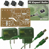
... This document contains the power supply specification, schematic, bill of materials, transformer documentation, printed circuit board layout, and performance data. Figure 1 – EP-16 Populated Circuit Board. Power Integrations Tel: +1 408 414 9660 Fax: +1 408 414 9760 www.powerint.com Figure 2 – EP-16 Assembled into Case with Cable (barrel − ...
Page 5
... Battery load, peak power mA W Measured at output peak power % o point 1.2/50 µs surge, IEC 1000-4- Ω series impedance, differential and common mode 100 kHz ring wave, 500 A short kV circuit current, differential and common mode o C Free convection, sea level 600 700 Power Integrations www.powerint.com ...
Page 6
... Note: EP-16 is designed for a battery load resistive or electronic load is used the supply may fail to start up at full load. This is normal. To ensure startup into a resistive load, increase the value µF (see circuit description for more information). Power Integrations Tel: +1 408 414 9660 Fax: +1 408 414 9760 www.powerint.com ...
Page 7
... In low power applications (less than approximately 1.5 W), a low value resistor may be used to provide sufficient conducted EMI filtering. A value in the range of 0 Ω Ω may be used. Page EPR-16 – LinkSwitch 2.75 W Charger/Adapter Power Integrations Tel: +1 408 414 9660 Fax: +1 408 414 9760 www.powerint.com ...
Page 8
... This filters noise associated with the supply to meet EN55022B / CISPR 22 B and FCC B conducted EMC limits, even when no Y safety capacitor is used. Ferrite bead L2 is optional, fitted to improve radiated EMI. Power Integrations Tel: +1 408 414 9660 Fax: +1 408 414 9760 www.powerint.com ...
Page 9
... CONTROL pin capacitor C3 will discharge and the supply will enter auto-restart. Page EPR-16 – LinkSwitch 2.75 W Charger/Adapter can be sensed directly the current into the CONTROL pin exceeds Tel: +1 408 414 9660 Fax: +1 408 414 9760 Power Integrations www.powerint.com ...
Page 10
... Stable dielectrics such as COG/NPO are acceptable but are costly when compared to a metalized plastic film capacitor. ∗ This includes LinkSwitch tolerance and line variation. Power Integrations Tel: +1 408 414 9660 Fax: +1 408 414 9760 www.powerint.com ∗ . ...
Page 11
... R1 was selected to program the peak power point to be 500 mA when a transformer with a nominal L value was used. Initial values are selected using the expression (from P Power Integrations Application note, AN-35): R1 ≅ (V The closest standard 1% series value of 20.5 kΩ was selected. See AN-35 for a more detailed explanation of clamp and feedback component selection. ...
Page 12
... EPR-16 - LinkSwitch 2.75 W Charger/Adapter 5 PCB Layout Figure 5 – EP-16 Printed Circuit Board Layout and Dimensions (0.001 inches). Power Integrations Tel: +1 408 414 9660 Fax: +1 408 414 9760 www.powerint.com 17-May-04 Page ...
Page 13
... Ferrite Bead – Fair-rite 2761008112 10 Ω Fusible – Vitrohm 253-4 series 100 Ω, 5%, 1/8 W 20.5 kΩ, 1%, 1 Ω, 5%, 1/4 W Custom EE13 – HiCal part # SIL6011 LNK501P – Power Integrations, Inc Not fitted Tel: +1 408 414 9660 Fax: +1 408 414 9760 Power Integrations www.powerint.com ...
Page 14
... AWG Figure 6 – Transformer Winding Diagram. 7.2 Electrical Specifications Electrical Strength Primary Inductance (Pin 1 to Pin 3) Resonant Frequency Primary Leakage Inductance (Pin 1 to Pin 4) Power Integrations Tel: +1 408 414 9660 Fax: +1 408 414 9760 www.powerint.com min, from Pins 1-3 to Pins ...
Page 15
... Tape: 3M 1298 Polyester Film (white) 290mils wide by 2.2 mils thick [8] Glue AV118 [9] Copper tape 6mm +/- 0.15 mm wide by 0.076 mm thick Design Notes: Power Integrations Device Frequency of Operation Mode Peak Current Reflected Voltage (Secondary to Primary) Maximum DC Input Voltage Minimum DC Input Votlage 7.4 Transformer Build Diagram Figure 7 – ...
Page 16
... Crop Unused Pins Remove pins 7 and 8 Note: The transformer is an integral part of the EMI performance of this design. Changes to the transformer may have significant impact on both conducted and radiated EMI. Power Integrations Tel: +1 408 414 9660 Fax: +1 408 414 9760 www.powerint.com 17-May-04 ...
Page 17
... Figure 8 – Load Regulation at Selected Input Voltages. Page EPR-16 – LinkSwitch 2.75 W Charger/Adapter Regulation Curve 200 300 400 Load Current (mA) Tel: +1 408 414 9660 Fax: +1 408 414 9760 85 VAC 115 VAC 190 VAC 230 VAC 265 VAC 500 600 Power Integrations www.powerint.com ...
Page 18
... No-Load Input Power 0.35 0.3 0.25 0.2 0.15 0.1 0. 100 Figure 10 – Zero Load Input Power vs. Input Line Voltage. Power Integrations Tel: +1 408 414 9660 Fax: +1 408 414 9760 www.powerint.com Efficiency vs. Output Current 200 300 400 Load Current (mA) No-Load Consumption 120 140 160 ...
Page 19
... Ch.1: LinkSwitch Drain-Source Voltage (100 V/div). Ch.3: LinkSwitch Drain-Source Current (0.1 A/div). and I DRAIN DRAIN V = 265 VAC 500 mA Ch.1: LinkSwitch Drain-Source Voltage (100 V/div). Ch.3: LinkSwitch Drain-Source Current (0.1 A/div). Tel: +1 408 414 9660 Fax: +1 408 414 9760 Waveforms Waveforms Power Integrations www.powerint.com ...
Page 20
... VAC 9.3 Load Transient Response (0. 0.5 A Load Step) Figure 15 – Dynamic Load Transient 0. 0.5 A step at V Ch.3: Output Voltage (500 mV/div). Power Integrations Tel: +1 408 414 9660 Fax: +1 408 414 9760 www.powerint.com Figure 14 – Output Voltage at Start-up, Battery . Model, V OUT_MAX Figure 16 – ...
Page 21
... EPR-16 – LinkSwitch 2.75 W Charger/Adapter Probe Ground (End cap and ground lead removed). (Modified with wires for probe ground for ripple measurement and two parallel decoupling capacitors added). Tel: +1 408 414 9660 Fax: +1 408 414 9760 Probe Tip Power Integrations www.powerint.com ...
Page 22
... 500 (Scale: 100 mV/div). Figure 21 – Output Voltage Ripple (Battery 115 VAC 5 500 mA (Scale: 100 mV, 5 ms,100 µs / div). Power Integrations Tel: +1 408 414 9660 Fax: +1 408 414 9760 www.powerint.com Figure 20 – Output Voltage Ripple (Resistive 230 VAC 5 515 (Scale: 100 mV/div). ...
Page 23
... Output Diode Thermocouple inserted into case above LinkSwitch Figure 23 - Thermal Image Measurements of Board and Sealed Adapter, 85 VAC Input, 5.3 V, 500 mA Output, 22 °C External Ambient Page EPR-16 – LinkSwitch 2.75 W Charger/Adapter Power Integrations Tel: +1 408 414 9660 Fax: +1 408 414 9760 www.powerint.com ...
Page 24
... Results with and without the optional components L2, R4 and C6 are shown to illustrate the improvement in radiated EMI (50 MHz to 60 MHz region). In all cases greater margin was obtained. Power Integrations Tel: +1 408 414 9660 Fax: +1 408 414 9760 www.powerint.com 17-May-04 ...
Page 25
... Power Point, Output Return Connected to Artificial Hand Input on LISN. 9.6.2 Optional Components Without Artificial Hand Figure 25 – EN55022 B / CISPR22 B, V Power Point, Output Floating. Page EPR-16 – LinkSwitch 2.75 W Charger/Adapter = 230 VAC Line, Peak IN = 230 VAC Line, Peak IN Power Integrations Tel: +1 408 414 9660 Fax: +1 408 414 9760 www.powerint.com ...
Page 26
... EPR-16 - LinkSwitch 2.75 W Charger/Adapter 9.6.3 Optional Components Removed With Artificial Hand Figure 26 - EN55022 B / CISPR22 B, V Power Point, Output Return Connected to Artificial Hand Input on LISN. Figure 27 - EN55022 B / CISPR22 B, V Power Integrations Tel: +1 408 414 9660 Fax: +1 408 414 9760 www.powerint.com = 230 VAC Line, Peak IN ...
Page 27
... Case will pop apart. Repeat on other side and pull to separate. Using diagonal cutter clip plastic and lift up as shown. Repeat on both sides of case (4 places). Case will then separate. Tel: +1 408 414 9660 Fax: +1 408 414 9760 Power Integrations www.powerint.com ...
Page 28
... The LNK520 has one key advantage over the LNK501. The internal MOSFET drive has been optimized to reduce high frequency radiated EMI. Typically improvement in radiated (>30 MHz) EMI performance is seen compared with the LNK501. Power Integrations Tel: +1 408 414 9660 Fax: +1 408 414 9760 www.powerint.com 17-May-04 ...
Page 29
... Increased leakage filtering to ensure supply enters auto-restart when output voltage is below region. Figure 30 – Modified EP-16: Low Cost, 2.75 W Cell Phone Charger Using the LNK520P. Page EPR-16 – LinkSwitch 2.75 W Charger/Adapter Power Integrations Tel: +1 408 414 9660 Fax: +1 408 414 9760 www.powerint.com ...
Page 30
... Figure 31 – Load Regulation at Selected Input Voltages (EP-16 Using the LNK520P). Power Integrations Tel: +1 408 414 9660 Fax: +1 408 414 9760 www.powerint.com 200 300 400 500 Load Current (mA) 17-May-04 85 VAC 115 VAC 190 VAC 230 VAC 265 VAC LNK501 (Max) ...
Page 31
... Page EPR-16 – LinkSwitch 2.75 W Charger/Adapter 300 400 500 600 700 Load Current (mA) Tel: +1 408 414 9660 Fax: +1 408 414 9760 Vin = 85 VAC Vin = 115 VAC Vin = 190 VAC Vin = 230 VAC Vin = 265 VAC 800 900 1000 Power Integrations www.powerint.com ...
Page 32
... VAC. 350 300 250 200 150 100 100 120 Figure 33 – Zero Load Input Power vs. Input Line Voltage. Power Integrations Tel: +1 408 414 9660 Fax: +1 408 414 9760 www.powerint.com 140 160 180 200 AC Input Voltage (VAC) 17-May-04 220 240 260 280 ...
Page 33
... Actual radiated emissions levels will vary according to radiated test setup and measurement configurations. LNK501P (EP-16) Figure 34 – Comparison of Radiated Emissions, V Page EPR-16 – LinkSwitch 2.75 W Charger/Adapter LNK520P (modified EP-16) = 230 VAC Line, Peak Power Point. IN Power Integrations Tel: +1 408 414 9660 Fax: +1 408 414 9760 www.powerint.com ...
Page 34
... PV 27-Aug-02 PV 14-Jan-03 CW 2-Apr-03 PV 25-Apr-03 AM 17-May-04 SH Power Integrations Tel: +1 408 414 9660 Fax: +1 408 414 9760 www.powerint.com Revision Description & changes 1.1 Transformer symbol dots moved on the schematic (Figure 5) 1.2 Caption to Figure 2 updated 1.3 Transformer pin out error corrected (Section 7.2) 1 ...
Page 35
... Page EPR-16 – LinkSwitch 2.75 W Charger/Adapter Notes Power Integrations Tel: +1 408 414 9660 Fax: +1 408 414 9760 www.powerint.com ...
Page 36
... For the latest updates, visit our Web site: www.powerint.com Power Integrations may make changes to its products at any time. Power Integrations has no liability arising from your use of any information, device or circuit described herein nor does it convey any license under its patent rights or the rights of others. ...