DAK-16A Power Integrations, DAK-16A Datasheet - Page 10
DAK-16A
Manufacturer Part Number
DAK-16A
Description
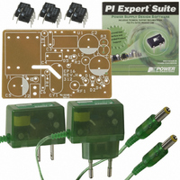
KIT DESIGN ACCELERATOR ADAPTER
Manufacturer
Power Integrations
Series
LinkSwitch®r
Specifications of DAK-16A
Main Purpose
AC/DC, Primary Side
Outputs And Type
1, Isolated
Power - Output
2.75W
Voltage - Output
5.5V
Current - Output
500mA
Voltage - Input
85 ~ 265VAC
Regulator Topology
Flyback
Frequency - Switching
42kHz
Board Type
Bare (Unpopulated)
Utilized Ic / Part
LNK500, LNK501, LNK520
Lead Free Status / RoHS Status
Not applicable / Not applicable
Other names
596-1001


EPR-16 - LinkSwitch 2.75 W Charger/Adapter
4.3 Transformer
The transformer is designed to always be discontinuous; all the energy is transferred to
the load during the MOSFET off time. The energy stored in the transformer during
discontinuous mode operation is ½·L·I²·f, where L is the primary inductance, I² is the peak
primary current squared and f is the switching frequency.
Since the value of LinkSwitch current limit and frequency directly determines the peak
power or CV/CC transition point in the output characteristic, the parameter of current
squared times frequency is defined in the datasheet. This parameter, together with the
output power, is used to specify the transformer primary inductance. With a primary
inductance tolerance of ±10%, the EP-16 is designed to provide the output current
characteristic shown in Figure 3
As LinkSwitch is powered by the energy stored in the leakage inductance of the
transformer, only a low cost two winding transformer is required. Leakage inductance
should be kept low, ideally at less than 2% of the primary inductance. High leakage
inductance will cause the CC characteristic to walk out as the output voltage decreases
and increases the no-load consumption of the supply.
With a figure of 50 µH for leakage, this design is able to meet a voltage tolerance of
±10% at the peak power point, including the effects of output cable drop. For tighter
voltage tolerance across the whole load range, a secondary optocoupler can be added.
For most battery charging applications, only the voltage at the peak power point is critical,
thus ensuring sufficient voltage for charging.
4.4 Clamp and Feedback Components
Diode D5 should either be a fast (t
across LinkSwitch from reversing and ringing below ground. A fast diode is preferred,
being lower cost. Leakage inductance is filtered by R2, the optimum value providing the
straightest CC characteristic.
Capacitor C4 is typically fixed at 0.1 µF and should be rated above the V
with both temperature and applied voltage. Low-cost, metalized plastic film capacitors
are ideal; high value, low-cost ceramic capacitors are not recommended. Dielectrics
used for these capacitors such as Z5U and Y5U are not stable and can cause output
instability as their value changes with voltage and temperature. Stable dielectrics such
as COG/NPO are acceptable but are costly when compared to a metalized plastic film
capacitor.
∗
This includes LinkSwitch tolerance and line variation.
Power Integrations
Tel: +1 408 414 9660 Fax: +1 408 414 9760
www.powerint.com
∗
.
rr
<250 ns) or ultra-fast type to prevent the voltage
OR
Page 10 of 36
and be stable
17-May-04
Related parts for DAK-16A
Image
Part Number
Description
Manufacturer
Datasheet
Request
R

Part Number:
Description:
KIT REF DES DPA 6.6W DC-DC CONV
Manufacturer:
Power Integrations
Datasheet:

Part Number:
Description:
KIT DESIGN ACCELERATOR POE CONV
Manufacturer:
Power Integrations
Datasheet:

Part Number:
Description:
DESIGN ACCELERATOR KIT XT SWITCH
Manufacturer:
Power Integrations
Datasheet:

Part Number:
Description:
DESIGN ACCELERATOR KIT LP SWITCH
Manufacturer:
Power Integrations
Datasheet:

Part Number:
Description:
KIT DESIGN ACC PEAKSWITCH FAMILY
Manufacturer:
Power Integrations
Datasheet:

Part Number:
Description:
KIT DESIGN ACCELERATOR ADAPTER
Manufacturer:
Power Integrations
Datasheet:

Part Number:
Description:
KIT DESIGN ACCELERATOR DC-DC
Manufacturer:
Power Integrations
Datasheet:

Part Number:
Description:
KIT DESIGN ACCELERATOR DPA SW
Manufacturer:
Power Integrations
Datasheet:

Part Number:
Description:
KIT DESIGN ACCELERATOR AC/DC PS
Manufacturer:
Power Integrations
Datasheet:

Part Number:
Description:
KIT DESIGN ACCELERATOR MODEM
Manufacturer:
Power Integrations
Datasheet: