DAK-16A Power Integrations, DAK-16A Datasheet - Page 8
DAK-16A
Manufacturer Part Number
DAK-16A
Description
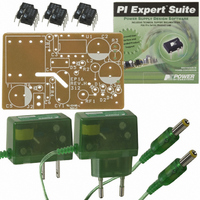
KIT DESIGN ACCELERATOR ADAPTER
Manufacturer
Power Integrations
Series
LinkSwitch®r
Specifications of DAK-16A
Main Purpose
AC/DC, Primary Side
Outputs And Type
1, Isolated
Power - Output
2.75W
Voltage - Output
5.5V
Current - Output
500mA
Voltage - Input
85 ~ 265VAC
Regulator Topology
Flyback
Frequency - Switching
42kHz
Board Type
Bare (Unpopulated)
Utilized Ic / Part
LNK500, LNK501, LNK520
Lead Free Status / RoHS Status
Not applicable / Not applicable
Other names
596-1001


EPR-16 - LinkSwitch 2.75 W Charger/Adapter
4 Circuit Description
The schematic shown in Figure 5 provides a CV/CC (constant voltage/constant current)
type output characteristic from a universal input voltage range of 85 VAC to 265 VAC.
The nominal peak power point at the transition from CC to CV is 5.5 V at 500 mA.
The precise output envelope specification is shown in Figure 3.
4.1 Input Stage
The incoming AC is rectified and filtered by D1-4, C1 and C2.
flameproof fusible type to protect against fault conditions and is a requirement to meet
safety agency fault testing. This component should be a wire wound type to withstand
input current surges while the input capacitors charge on application of power or during
withstand line-transient testing. Metal film type resistors are not recommended, they do
not have the transient dissipation capabilities required and may fail prematurely in the
field.
Lower values increase the resistor dissipation (V²/R power term) during transients,
increasing resistor stress, while higher values increase steady state dissipation (I²R
power term) and reduce efficiency.
If a suitable flame proof resistor cannot be found (during failure flame proof resistors do
not emit flames, smoke or incandescent material that may damage transformer
insulation), then a standard fusible type may be used as long as a protective heat shrink
sleeve is placed over the resistor. Please consult with a safety engineer or local safety
agency.
The value of C1 and C2 were selected to provide the smallest standard values to meet
3 µF/W, in this case two 4.7 µF, 400 V capacitors. Smaller values are possible (either
2.2 µF or 3.3 µF) however, the lower DC rail voltage will increase LinkSwitch dissipation,
lowering efficiency and increasing line frequency output ripple. Differential mode EMI
(<500 kHz) also typically increases.
The input capacitance is split between C1 and C2 to allow an input π filter to be formed
by L1.
CISPR 22 B and FCC B conducted EMC limits, even when no Y safety capacitor is used.
Ferrite bead L2 is optional, fitted to improve radiated EMI.
Power Integrations
Tel: +1 408 414 9660 Fax: +1 408 414 9760
www.powerint.com
This filters noise associated with the supply to meet EN55022B /
Resistor RF1 is a
Page 8 of 36
17-May-04
Related parts for DAK-16A
Image
Part Number
Description
Manufacturer
Datasheet
Request
R

Part Number:
Description:
KIT REF DES DPA 6.6W DC-DC CONV
Manufacturer:
Power Integrations
Datasheet:

Part Number:
Description:
KIT DESIGN ACCELERATOR POE CONV
Manufacturer:
Power Integrations
Datasheet:

Part Number:
Description:
DESIGN ACCELERATOR KIT XT SWITCH
Manufacturer:
Power Integrations
Datasheet:

Part Number:
Description:
DESIGN ACCELERATOR KIT LP SWITCH
Manufacturer:
Power Integrations
Datasheet:

Part Number:
Description:
KIT DESIGN ACC PEAKSWITCH FAMILY
Manufacturer:
Power Integrations
Datasheet:

Part Number:
Description:
KIT DESIGN ACCELERATOR ADAPTER
Manufacturer:
Power Integrations
Datasheet:

Part Number:
Description:
KIT DESIGN ACCELERATOR DC-DC
Manufacturer:
Power Integrations
Datasheet:

Part Number:
Description:
KIT DESIGN ACCELERATOR DPA SW
Manufacturer:
Power Integrations
Datasheet:

Part Number:
Description:
KIT DESIGN ACCELERATOR AC/DC PS
Manufacturer:
Power Integrations
Datasheet:

Part Number:
Description:
KIT DESIGN ACCELERATOR MODEM
Manufacturer:
Power Integrations
Datasheet: