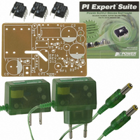
DAK-16A Power Integrations, DAK-16A Datasheet - Page 2

DAK-16A
Manufacturer Part Number
DAK-16A
Description
KIT DESIGN ACCELERATOR ADAPTER
Manufacturer
Power Integrations
Series
LinkSwitch®r
Specifications of DAK-16A
Main Purpose
AC/DC, Primary Side
Outputs And Type
1, Isolated
Power - Output
2.75W
Voltage - Output
5.5V
Current - Output
500mA
Voltage - Input
85 ~ 265VAC
Regulator Topology
Flyback
Frequency - Switching
42kHz
Board Type
Bare (Unpopulated)
Utilized Ic / Part
LNK500, LNK501, LNK520
Lead Free Status / RoHS Status
Not applicable / Not applicable
Other names
596-1001
EPR-16 - LinkSwitch 2.75 W Charger/Adapter
1
2
3
4
5
6
7
8
9
10 Appendix A – EP-16 Enclosure Opening Procedures ..............................................27
11
4.1
4.2
4.3
4.4
4.5
7.1
7.2
7.3
7.4
7.5
8.1
8.2
8.3
9.1
9.2
9.3
9.4
9.5
9.6
10.1
10.2
11.1
11.2
11.3
11.4
Introduction.................................................................................................................4
Power Supply Specification ........................................................................................5
Schematic...................................................................................................................7
Circuit Description ......................................................................................................8
PCB Layout ..............................................................................................................12
Bill Of Materials ........................................................................................................13
Transformer ..............................................................................................................14
Performance Data ....................................................................................................17
Waveforms ...............................................................................................................19
9.1.1
9.1.2
9.4.1
9.4.2
9.6.1
9.6.2
9.6.3
11.4.1
11.4.2
Appendix B – LNK520P in the High-Side Configuration ..........................................28
Input Stage ..........................................................................................................8
LinkSwitch Operation ..........................................................................................9
Transformer.......................................................................................................10
Clamp and Feedback Components ...................................................................10
Output Stage .....................................................................................................11
Transformer Winding .........................................................................................14
Electrical Specifications.....................................................................................14
Materials............................................................................................................15
Transformer Build Diagram ...............................................................................15
Transformer Construction..................................................................................16
Line and Load Regulation..................................................................................17
Efficiency ...........................................................................................................18
No-Load Input Power ........................................................................................18
Drain Voltage and Current Waveforms..............................................................19
Output Voltage Start-up Profile..........................................................................20
Load Transient Response (0.25 A to 0.5 A Load Step) .....................................20
Output Ripple Measurements............................................................................21
Thermal Measurements ....................................................................................23
Conducted EMI..................................................................................................24
Method 1 - Non-destructive ...............................................................................27
Method 2 - Destructive ......................................................................................27
Introduction........................................................................................................28
Comparison of LNK501 and LNK520 ................................................................28
Circuit Changes.................................................................................................29
Performance Data .............................................................................................30
Power Integrations
Tel: +1 408 414 9660 Fax: +1 408 414 9760
www.powerint.com
90 VAC, Normal Operation.........................................................................19
265 VAC, Normal Operation.......................................................................19
Ripple Measurement Technique ................................................................21
Output Voltage Ripple ................................................................................22
Optional Components With Artificial Hand .................................................25
Optional Components Without Artificial Hand ............................................25
Optional Components Removed With Artificial Hand .................................26
Line and Load Regulation ..........................................................................30
Efficiency....................................................................................................31
Table Of Contents
Page 2 of 36
17-May-04


