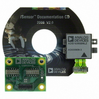
ADIS16365/PCBZ Analog Devices Inc, ADIS16365/PCBZ Datasheet - Page 10

ADIS16365/PCBZ
Manufacturer Part Number
ADIS16365/PCBZ
Description
BOARD INTERFACE FOR ADIS16365
Manufacturer
Analog Devices Inc
Series
iMEMS®, iSensor™r
Specifications of ADIS16365/PCBZ
Sensor Type
Accelerometer, Gyroscope, 3 Axis
Sensing Range
±17g, ±75°/sec, ±150°/sec, ±300°/sec
Interface
SPI Serial
Sensitivity
3.3mg/LSB, 0.0125 ~ 0.05°/sec/LSB
Voltage - Supply
4.75 V ~ 5.25 V
Embedded
No
Utilized Ic / Part
ADIS16365
Silicon Manufacturer
Analog Devices
Application Sub Type
Accelerometer / Gyroscope
Kit Application Type
Sensing - Motion / Vibration / Shock
Silicon Core Number
ADIS16365
Lead Free Status / RoHS Status
Not applicable / RoHS Compliant
For Use With
ADISUSBZ - KIT EVAL ADIS W/SOFTWARE USB
Lead Free Status / RoHS Status
Lead free / RoHS Compliant, Not applicable / RoHS Compliant
ADIS16360/ADIS16365
MEMORY MAP
Table 8. User Register Memory Map
Name
FLASH_CNT
SUPPLY_OUT
XGYRO_OUT
YGYRO_OUT
ZGYRO_OUT
XACCL_OUT
YACCL_OUT
ZACCL_OUT
XTEMP_OUT
YTEMP_OUT
ZTEMP_OUT
AUX_ADC
Reserved
XGYRO_OFF
YGYRO_OFF
ZGYRO_OFF
XACCL_OFF
YACCL_OFF
ZACCL_OFF
ALM_MAG1
ALM_MAG2
ALM_SMPL1
ALM_SMPL2
ALM_CTRL
AUX_DAC
GPIO_CTRL
MSC_CTRL
SMPL_PRD
SENS_AVG
SLP_CNT
DIAG_STAT
GLOB_CMD
Reserved
LOT_ID1
LOT_ID2
PROD_ID
PROD_ID
SERIAL_NUM
1
Each register contains two bytes. The address of the lower byte is displayed. The address of the upper byte is equal to the address of the lower byte plus 1.
User Access
Read only
Read only
Read only
Read only
Read only
Read only
Read only
Read only
Read only
Read only
Read only
Read only
N/A
Read/write
Read/write
Read/write
Read/write
Read/write
Read/write
Read/write
Read/write
Read/write
Read/write
Read/write
Read/write
Read/write
Read/write
Read/write
Read/write
Write only
Read only
Write only
N/A
Read only
Read only
Read only
Read only
Read only
Flash Backup
Yes
No
No
No
No
No
No
No
No
No
No
No
N/A
Yes
Yes
Yes
Yes
Yes
Yes
Yes
Yes
Yes
Yes
Yes
No
No
Yes
Yes
Yes
No
No
No
N/A
Yes
Yes
Yes
Yes
Yes
Address
0x2A
0x2C
0x32
0x36
0x38
0x3C
0x40 to 0x51
0x58
0x00
0x02
0x04
0x06
0x08
0x0A
0x0C
0x0E
0x10
0x12
0x14
0x16
0x18
0x1A
0x1C
0x1E
0x20
0x22
0x24
0x26
0x28
0x2E
0x30
0x34
0x3A
0x3E
0x52
0x54
0x56
0x56
1
Rev. D | Page 10 of 20
Default
N/A
N/A
N/A
N/A
N/A
N/A
N/A
N/A
N/A
N/A
N/A
N/A
N/A
0x0000
0x0000
0x0000
0x0000
0x0000
0x0000
0x0000
0x0000
0x0000
0x0000
0x0000
0x0000
0x0000
0x0006
0x0001
0x0402
0x0000
0x0000
0x0000
N/A
N/A
N/A
0x3FE8
0x3FED
N/A
Register Description
Flash memory write count
Power supply measurement
X-axis gyroscope output
Y-axis gyroscope output
Z-axis gyroscope output
X-axis accelerometer output
Y-axis accelerometer output
Z-axis accelerometer output
X-axis gyroscope temperature output
Y-axis gyroscope temperature output
Z-axis gyroscope temperature output
Auxiliary ADC output
Reserved
X-axis gyroscope bias offset factor
Y-axis gyroscope bias offset factor
Z-axis gyroscope bias offset factor
X-axis acceleration bias offset factor
Y-axis acceleration bias offset factor
Z-axis acceleration bias offset factor
Alarm 1 amplitude threshold
Alarm 2 amplitude threshold
Alarm 1 sample size
Alarm 2 sample size
Alarm control
Auxiliary DAC data
Auxiliary digital input/output control
Data ready, self-test, miscellaneous
Internal sample period (rate) control
Dynamic range and digital filter control
Sleep mode control
System status
System commands
Reserved
Lot Identification Code 1
Lot Identification Code 2
Product identification, ADIS16360
Product identification, ADIS16365
Serial number
Bit Function
N/A
See Table 9
See Table 9
See Table 9
See Table 9
See Table 9
See Table 9
See Table 9
See Table 9
See Table 9
See Table 9
See Table 9
N/A
See Table 15
See Table 15
See Table 15
See Table 16
See Table 16
See Table 16
See Table 27
See Table 27
See Table 28
See Table 28
See Table 29
See Table 23
See Table 21
See Table 22
See Table 18
See Table 20
See Table 19
See Table 26
See Table 17
N/A
See Table 32
See Table 32
See Table 32
See Table 32
See Table 32


