ADIS16365/PCBZ Analog Devices Inc, ADIS16365/PCBZ Datasheet - Page 12
ADIS16365/PCBZ
Manufacturer Part Number
ADIS16365/PCBZ
Description
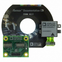
BOARD INTERFACE FOR ADIS16365
Manufacturer
Analog Devices Inc
Series
iMEMS®, iSensor™r
Specifications of ADIS16365/PCBZ
Sensor Type
Accelerometer, Gyroscope, 3 Axis
Sensing Range
±17g, ±75°/sec, ±150°/sec, ±300°/sec
Interface
SPI Serial
Sensitivity
3.3mg/LSB, 0.0125 ~ 0.05°/sec/LSB
Voltage - Supply
4.75 V ~ 5.25 V
Embedded
No
Utilized Ic / Part
ADIS16365
Silicon Manufacturer
Analog Devices
Application Sub Type
Accelerometer / Gyroscope
Kit Application Type
Sensing - Motion / Vibration / Shock
Silicon Core Number
ADIS16365
Lead Free Status / RoHS Status
Not applicable / RoHS Compliant
For Use With
ADISUSBZ - KIT EVAL ADIS W/SOFTWARE USB
Lead Free Status / RoHS Status
Lead free / RoHS Compliant, Not applicable / RoHS Compliant


ADIS16360/ADIS16365
CALIBRATION
Manual Bias Calibration
The bias offset registers in Table 15 and Table 16 provide a
manual adjustment function for the output of each sensor. For
example, if XGYRO_OFF = 0x1FF6 (DIN = 0x9B1F, 0x9AF6),
the XGYRO_OUT offset shifts by −10 LSBs, or −0.125°/sec.
Table 15. XGYRO_OFF, YGYRO_OFF, ZGYRO_OFF
Bit Descriptions
Bits
[15:13]
[12:0]
Table 16. XACCL_OFF, YACCL_OFF, ZACCL_OFF
Bit Descriptions
Bits
[15:12]
[11:0]
Gyroscope Automatic Bias Null Calibration
Set GLOB_CMD[0] = 1 (DIN = 0xBE01) to execute the auto-
matic bias null calibration function. This function measures all
three gyroscope output registers and then loads each gyroscope
offset register with the opposite value to provide a quick bias
calibration. All sensor data is then reset to 0, and the flash
memory is updated automatically within 50 ms (see Table 17).
Gyroscope Precision Automatic Bias Null Calibration
Set GLOB_CMD[4] = 1 (DIN = 0xBE10) to execute the precision
automatic bias null calibration function. This function takes the
sensor offline for 30 sec while it collects a set of data and calculates
more accurate bias correction factors for each gyroscope. After
this function is executed, the newly calculated correction factor
is loaded into the gyroscope offset registers, all sensor data is
reset to 0, and the flash memory is updated automatically within
50 ms (see Table 17).
Restoring Factory Calibration
Set GLOB_CMD[1] = 1 (DIN = 0xBE02) to execute the factory
calibration restore function. This function resets each user cali-
bration register to 0x0000 (see Table 15 and Table 16), resets all
sensor data to 0, and automatically updates the flash memory
within 50 ms (see Table 17).
Linear Acceleration Bias Compensation (Gyroscope)
Set MSC_CTRL[7] = 1 (DIN = 0xB486) to enable correction for
low frequency acceleration influences on gyroscope bias. The
DIN sequence also preserves the factory default condition for
the data ready function (see Table 22).
Description (Default = 0x0000)
Not used.
Data bits. Twos complement, 0.0125°/sec per LSB.
Typical adjustment range = ±50°/sec.
Description (Default = 0x0000)
Not used.
Data bits. Twos complement, 3.333 mg/LSB.
Typical adjustment range = ±6.7 g.
Rev. D | Page 12 of 20
OPERATIONAL CONTROL
Global Commands
The GLOB_CMD register provides trigger bits for several use-
ful functions. Setting the assigned bit to 1 starts each operation,
which returns the bit to 0 after completion. For example, set
GLOB_CMD[7] = 1 (DIN = 0xBE80) to execute a software reset,
which stops the sensor operation and runs the device through
its start-up sequence. This sequence includes loading the control
registers with the data in their respective flash memory locations
prior to producing new data. Reading the GLOB_CMD register
(DIN = 0x3E00) starts the burst read sequence.
Table 17. GLOB_CMD Bit Descriptions
Bits
[15:8]
[7]
[6:5]
[4]
[3]
[2]
[1]
[0]
Internal Sample Rate
The SMPL_PRD register provides discrete sample period settings
using the bit assignments in Table 18 and the following equation:
To calculate the internal sample rate, divide 1 by the sample
period (t
sample rate is 149 SPS.
Table 18. SMPL_PRD Bit Descriptions
Bits
[15:8]
[7]
[6:0]
The default sample rate setting of 819.2 SPS preserves the sensor
bandwidth and provides optimal performance. For systems that
value slower sample rates, keep the internal sample rate at
819.2 SPS. Use the programmable filter (SENS_AVG) to reduce
the bandwidth, which helps to prevent aliasing. The data ready
function (MSC_CTRL) can drive an interrupt routine that uses
a counter to help ensure data coherence at the reduced rates.
t
S
= t
S
B
). For example, when SMPL_PRD[7:0] = 0x0A, the
Description (Default = 0x0000)
Software reset command
Precision autonull command
Factory calibration restore command
Not used
Not used
Flash update command (see the Device Configuration
section)
Auxiliary DAC data latch (see the Auxiliary DAC section)
Autonull command
Description (Default = 0x0001)
Not used
Time base (t
0 = 0.61035 ms, 1 = 18.921 ms
Increment setting (N
Internal sample period = t
× (N
S
+ 1)
B
)
S
)
S
= t
B
× (N
S
+ 1)
Related parts for ADIS16365/PCBZ
Image
Part Number
Description
Manufacturer
Datasheet
Request
R

Part Number:
Description:
±1.7g Dual-Axis IMEMS Accelerometer Evaluation Board
Manufacturer:
Analog Devices Inc
Datasheet:

Part Number:
Description:
Inertial Sensor Evaluation System
Manufacturer:
Analog Devices Inc
Datasheet:
Part Number:
Description:
Manufacturer:
Analog Devices Inc
Datasheet:
Part Number:
Description:
Manufacturer:
Analog Devices Inc
Datasheet:
Part Number:
Description:
Manufacturer:
Analog Devices Inc
Datasheet:
Part Number:
Description:
Manufacturer:
Analog Devices Inc
Datasheet:
Part Number:
Description:
Manufacturer:
Analog Devices Inc
Datasheet:
Part Number:
Description:
Manufacturer:
Analog Devices Inc
Datasheet:
Part Number:
Description:
Manufacturer:
Analog Devices Inc
Datasheet:
Part Number:
Description:
Manufacturer:
Analog Devices Inc
Datasheet:
Part Number:
Description:
Manufacturer:
Analog Devices Inc
Datasheet:
Part Number:
Description:
Manufacturer:
Analog Devices Inc
Datasheet:
Part Number:
Description:
Manufacturer:
Analog Devices Inc
Datasheet: