CYII5SC1300-EVAL Cypress Semiconductor Corp, CYII5SC1300-EVAL Datasheet - Page 15
CYII5SC1300-EVAL
Manufacturer Part Number
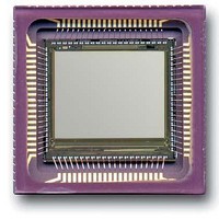
CYII5SC1300-EVAL
Description
BOARD EVAL IMG SENS IBIS5-B-1300
Manufacturer
Cypress Semiconductor Corp
Specifications of CYII5SC1300-EVAL
Sensor Type
CMOS Imaging, Color (RGB)
Sensing Range
1.3 Megapixel
Interface
Parallel/Serial
Sensitivity
106 fps
Voltage - Supply
3 V ~ 4.5 V
Embedded
No
Utilized Ic / Part
IBIS5-B-1300
Lead Free Status / RoHS Status
Contains lead / RoHS non-compliant
Lead Free Status / RoHS Status
Lead free / RoHS Compliant, Contains lead / RoHS non-compliant


Document #: 38-05710 Rev. *A
X_REG Register (10:0)
The X_REG register determines the start position of the
window in the X-direction. In this direction, there are 640
possible starting positions (2 pixels are addressed at the same
time in one clock cycle). If sub sampling is enabled only the
even pixels can be set as starting position (for instance: 0, 2,
4, 6, 8… 638).
YL_REG (10:0) and YR_REG (10:0)
The YL_REG and YR_REG registers determine the start
position of the window in the Y-direction. In this direction, there
are 1024 possible starting positions. In rolling shutter mode the
YL_REG register sets the start position of the read (left)
pointer and the YR_REG sets the start position of the reset
(right) pointer. For both shutter types YL_REG must always be
equal to YR_REG.
Image Core Register (7:0)
Bits 1:0 of the IMAGE_CORE register define the test mode of
the image core. Setting 00 is the default and normal operation
mode. In case the bit is set to 1, the odd (bit 1) or even (bit 0)
columns are tight to the reset level. If the internal ADC is used
bits 0 and 1 can be used to create test pattern to test the
sample moment of the ADC. If the ADC sample moment is not
chosen correctly the created test pattern will not be
black-white-black-etc. (IMAGE_CORE register set at 1 or 2) or
black-black-white-white-black-black (IMAGE_CORE register
set at 9) but grey shadings if the sensor is saturated.
Bits 7:2 of the IMAGE_CORE register define the sub-sampling
mode in the X-direction (bits 4:2) and in the Y-direction (bits
7:5). The sub-sampling modes and corresponding bit setting
are given in
Amplifier Register (6:0)
1. GAIN (bits 3:0)
2. UNITY (bit 4)
3. DUAL_OUT (bit 5)
The gain bits determine the gain setting of the output am-
plifier. They are only effective if UNITY = 0. The gains and
corresponding bit setting are given in
In case UNITY = 1, the gain setting of GAIN is bypassed
and the gain amplifier is put in unity feedback.
If DUAL_OUT = 1, the two output amplifiers are active. If
DUAL_OUT = 0, the signals from the two buses are multi-
plexed to output PXL_OUT1 which must be connected to
ADC_IN. The gain amplifier and output driver of the second
path are put in standby.
Table 6
(Section ) and
Table 7
Table 8
(Section ).
Figure 16. Parallel Interface Timing
(Section ).
DAC_RAW Register (6:0) and DAC_FINE (6:0) Register
These registers determine the black reference level at the
output of the output amplifier. Bit setting 1111111 for
DAC_RAW register gives the highest offset voltage, bit setting
0000000 for DAC_RAW register gives the lowest offset
voltage. Ideally, if the two output paths have no offset
mismatch, the DAC_FINE register must be set to 1000000.
Deviation from this value can be used to compensate the
internal mismatch (see
ADC Register (2:0)
Data Interfaces
Two different data interfaces are implemented. They can be
selected using pins IF_MODE (pin 12) and SER_MODE (pin
6).
Table 14.Serial and Parallel Interface Selection
Parallel Interface
The parallel interface uses a 16-bit parallel input (P_DATA
<15:0>) to upload new register values. Asserting P_WRITE
loads the parallel data into the internal register of the
IBIS5-B-1300 where it is decoded. (See
(15:12) Address bits REG_ADDR (3:0); P_DATA (11:0) Data
bits REG_DATA (11:0)).
4. STANDBY
1. TRISTATE_OUT (bit 0)
2. GAMMA (bit 1)
3. BIT_INV (bit 2)
If STANDBY = 0, the complete output amplifier is put in
standby. For normal use, STANDBY must be set to 1.
In case TRISTATE = 0, the ADC_D<9:0> outputs are in
tri-state mode. TRISTATE = 1 for normal operation mode.
If GAMMA is set to 1, the ADC input to output conversion
is linear; otherwise the conversion follows a 'gamma' law
(more contrast in dark parts of the window, lower contrast
in the bright parts).
If BIT_INV = 1, 0000000000 is the conversion of the lowest
possible input voltage, otherwise the bits are inverted.
IF_MODE
1
0
0
SER_MODE
“Output Amplifier” on page
X
1
0
CYII5FM1300AB
Parallel
Serial 3 Wire
Serial 2 Wire.
IBIS5-B-1300
Selected interface
Figure
Page 15 of 42
16. P_DATA
7).
[+] Feedback
Related parts for CYII5SC1300-EVAL
Image
Part Number
Description
Manufacturer
Datasheet
Request
R

Part Number:
Description:
Manufacturer:
Cypress Semiconductor Corp
Datasheet:
Part Number:
Description:
Manufacturer:
Cypress Semiconductor Corp
Datasheet:
Part Number:
Description:
Manufacturer:
Cypress Semiconductor Corp
Datasheet:
Part Number:
Description:
Manufacturer:
Cypress Semiconductor Corp
Datasheet:
Part Number:
Description:
Manufacturer:
Cypress Semiconductor Corp
Datasheet: