CYII5SC1300-EVAL Cypress Semiconductor Corp, CYII5SC1300-EVAL Datasheet - Page 6
CYII5SC1300-EVAL
Manufacturer Part Number
CYII5SC1300-EVAL
Description
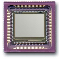
BOARD EVAL IMG SENS IBIS5-B-1300
Manufacturer
Cypress Semiconductor Corp
Specifications of CYII5SC1300-EVAL
Sensor Type
CMOS Imaging, Color (RGB)
Sensing Range
1.3 Megapixel
Interface
Parallel/Serial
Sensitivity
106 fps
Voltage - Supply
3 V ~ 4.5 V
Embedded
No
Utilized Ic / Part
IBIS5-B-1300
Lead Free Status / RoHS Status
Contains lead / RoHS non-compliant
Lead Free Status / RoHS Status
Lead free / RoHS Compliant, Contains lead / RoHS non-compliant


Document #: 38-05710 Rev. *A
X-Addressing
Because of the high pixel rate, the X-shift register selects 2
columns at the time for readout, so it runs at half the system
clock speed. All even columns are connected to bus A; all odd
columns to bus B. In the output amplifier, bus A and bus B are
combined into one stream of pixel data at system clock speed.
At the end of the row blanking time, the X_SYNC switch is
closed while all other switches are open and the decoder
output is fed to the register. The decoder loads a logical one
in one of the registers and a logical zero in the rest. This
defines the starting point of the window in the X direction. As
soon as the X_SYNC signal is released, the register starts
shifting from the start position.
When no sub-sampling is required, X_SUB is inactive. he
pointer in the shift-register moves 1 bit at the time.
When sub-sampling is enabled, X_SUB is activated. The shift
register moves 2 bits at the time. Taking into account that every
register selects 2 columns, hence 2 pixels sub-sampling
results in the pattern “XXOOXXOO” when 8 pixels are
considered. Suppose the columns are numbered from left to
right starting with 0 (zero) and sub-sampling is enabled:
If columns 1 and 2, 5 and 6, 9 and 10 … are swapped using
the SWAP_12 switches, a normal sub-sampling pattern of
“XOXOXOXO” is obtained.
If columns 3 and 4, 7 and 8, 11 and 12 … are swapped using
the SWAP_30 switches, the pattern is “OXOXOXOX”.
SYS_CLOCK
X_SYNC
X_SUB
X_SWAP30
X_SWAP12
BUS_A
BUS_B
1/2
Reg(n)
Figure 6. Column Structure
A
COL(i)
B
DEC(n+1)
Reg(n+1)
COL(i+1)
If both the SWAP_12 and SWAP_30 switches are closed,
pattern “OOXXOOXX” is obtained.
Because every register addresses 2 columns at the time, the
addressable pixels range in sub-sample mode is from 0 to half
the maximum number of pixels in a row (only even values). For
instance: 0, 2, 4, 6, 8… 638.
Table 6. X–Sub-sample Patterns
Y-addressing
For symmetry reasons, the sub-sampling modes in the
Y-direction are the same as in X-direction.
Table 7. Y–Sub-sample Patterns
A
X_SUB
Y_SUB
COL(i+2)
0
1
1
1
1
0
1
1
B
DEC(n+2)
Reg(n+2)
Y_SWAP12 Y_SWAP30 Sub-sample Pattern
X_SWAP12 X_SWAP30 Sub-sample Pattern
COL(i+3)
A
0
0
1
0
0
1
0
1
B
Column
amplifiers
0
0
0
0
0
0
1
1
Output
amplifier
CYII5FM1300AB
IBIS5-B-1300
XXOOXXOO
XOXOXOXO
XXXXXXXX
XXOOXXOO
XOXOXOXO
OXOXOXOX
OOXXOOXX
XXXXXXXX
Page 6 of 42
[+] Feedback
Related parts for CYII5SC1300-EVAL
Image
Part Number
Description
Manufacturer
Datasheet
Request
R

Part Number:
Description:
Manufacturer:
Cypress Semiconductor Corp
Datasheet:
Part Number:
Description:
Manufacturer:
Cypress Semiconductor Corp
Datasheet:
Part Number:
Description:
Manufacturer:
Cypress Semiconductor Corp
Datasheet:
Part Number:
Description:
Manufacturer:
Cypress Semiconductor Corp
Datasheet:
Part Number:
Description:
Manufacturer:
Cypress Semiconductor Corp
Datasheet: