DM300019 Microchip Technology, DM300019 Datasheet - Page 30
DM300019
Manufacturer Part Number
DM300019
Description
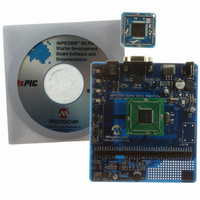
BOARD DEMO DSPICDEM 80L STARTER
Manufacturer
Microchip Technology
Type
MCUr
Specifications of DM300019
Contents
Board, CD, Sample Part
Processor To Be Evaluated
dsPIC30F and dsPIC33F
Interface Type
RS-232
Silicon Manufacturer
Microchip
Silicon Core Number
DsPIC30F6014A, DsPIC33FJ256GP710
Silicon Family Name
DsPIC30F And DsPIC33F
Kit Contents
Development Board And Docs On CD
Rohs Compliant
Yes
Lead Free Status / RoHS Status
Lead free / RoHS Compliant
For Use With/related Products
dsPIC30F, dsPIC33F
Lead Free Status / Rohs Status
Lead free / RoHS Compliant
Available stocks
Company
Part Number
Manufacturer
Quantity
Price
Company:

Part Number:
DM300019
Manufacturer:
Microchip Technology
Quantity:
135
Company:
Part Number:
DM300019
Manufacturer:
MICROCHIP
Quantity:
12 000


dsPICDEM™ 80-Pin Starter Development Board User’s Guide
DS51584B-page 26
The dsPIC DSC device functionality used in this demonstration program includes:
• Setting up I/O ports
• Setting up timer interrupts
• Handling interrupts
To observe this demonstration, close jumper J4 to enable the LEDs, then operate the
switches.
3.3.2
To illustrate analog-to-digital conversion, the analog value of potentiometer R13 is
converted by the Analog-to-Digital Converter, ADC12, to a digital value that is
transmitted via UART1 to a PC.
When the HyperTerminal accessory in Microsoft Windows
port on the dsPICDEM 80-Pin Starter Development Board, it receives and displays a
stream of three-digit HEX codes that correspond to the 12-bit output value of ADC12.
As the potentiometer R13 is adjusted, the displayed HEX code changes within a range
from 000 to FFF.
The dsPIC30F device functionality used for this demonstration includes:
• Conversion of an analog signal to a 12-bit digital signal
• Conversion of the 12-bit ADC value to HEX and ASCII format
• UART communication handling
To implement this demonstration, connect the J1 connector on the dsPICDEM 80-Pin
Starter Development Board to the RS-232 serial port on the PC with a DB9 cable. Using
the HyperTerminal program available as a Microsoft Windows communications
accessory, configure the serial port to 2400 baud, 8 bits with 1 stop bit, no parity and
no flow control.
3.3.3
To illustrate digital-to-analog conversion, the dsPICDEM 80-Pin Starter Development
Board uses the MCP41010 digital potentiometer and MCP6022 Operational Amplifier
(configured as a low-pass filter) to deliver an audio tone to the LINE OUT pin. The
digital input is derived from a table of HEX values in data memory. The demo program
cycles through the table and delivers the selected value to the digital potentiometer via
the Serial Peripheral Interface (SPI) module on the dsPIC DSC device. The table
values cover the full range of the digital potentiometer.
The program communicates a new table value to the digital potentiometer every 125
microseconds, which generates a 400 Hz audio signal out of the low-pass filter.
Switches S1 and S2 are used to change the output frequency to 800 Hz and 1600 Hz,
respectively.
The dsPIC DSC device functionality used for this demonstration includes:
• Mapping of data memory to program memory with PSV addressing
• Initialization of the SPI port
• Loading and transmission of data using hardware SPI
To observe this demonstration, connect an oscilloscope probe to pin 2 of J9 (the LINE
OUT pin).
Analog-to-Digital Conversion
Digital-to-Analog Conversion
®
© 2006 Microchip Technology Inc.
is connected to the serial
Related parts for DM300019
Image
Part Number
Description
Manufacturer
Datasheet
Request
R

Part Number:
Description:
Manufacturer:
Microchip Technology Inc.
Datasheet:
Part Number:
Description:
Manufacturer:
Microchip Technology Inc.
Datasheet:
Part Number:
Description:
Manufacturer:
Microchip Technology Inc.
Datasheet:
Part Number:
Description:
Manufacturer:
Microchip Technology Inc.
Datasheet:
Part Number:
Description:
Manufacturer:
Microchip Technology Inc.
Datasheet:
Part Number:
Description:
Manufacturer:
Microchip Technology Inc.
Datasheet:
Part Number:
Description:
Manufacturer:
Microchip Technology Inc.
Datasheet:
Part Number:
Description:
Manufacturer:
Microchip Technology Inc.
Datasheet: