DM300019 Microchip Technology, DM300019 Datasheet - Page 34
DM300019
Manufacturer Part Number
DM300019
Description
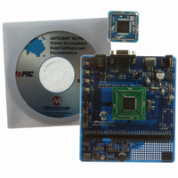
BOARD DEMO DSPICDEM 80L STARTER
Manufacturer
Microchip Technology
Type
MCUr
Specifications of DM300019
Contents
Board, CD, Sample Part
Processor To Be Evaluated
dsPIC30F and dsPIC33F
Interface Type
RS-232
Silicon Manufacturer
Microchip
Silicon Core Number
DsPIC30F6014A, DsPIC33FJ256GP710
Silicon Family Name
DsPIC30F And DsPIC33F
Kit Contents
Development Board And Docs On CD
Rohs Compliant
Yes
Lead Free Status / RoHS Status
Lead free / RoHS Compliant
For Use With/related Products
dsPIC30F, dsPIC33F
Lead Free Status / Rohs Status
Lead free / RoHS Compliant
Available stocks
Company
Part Number
Manufacturer
Quantity
Price
Company:

Part Number:
DM300019
Manufacturer:
Microchip Technology
Quantity:
135
Company:
Part Number:
DM300019
Manufacturer:
MICROCHIP
Quantity:
12 000


dsPICDEM™ 80-Pin Starter Development Board User’s Guide
3.5
DS51584B-page 30
BOARD SELF-TEST
The board self-test is provided for completeness only. Users do not need to run this
test.
1. Power the board using a 9V DC supply and the barrel power connector.
2. Using a DMM set for DCV, check that 3.3V or 5.0V is available at location marked
3. Connect a shorting plug on the RS-232 connector J1. This shorting plug should
4. Short pins 2 and 3 on line connector J9 using a 0.1″ jumper.
5. Make sure J4 has a 0.1″ jumper on it.
6. To enter the Self-Test mode, hold down S1, press and release MCLR, then
The following four tests should run:
UART Test
Keypad Test
Potentiometer Test During this test, LED RD6 blinks rapidly. You must first respond by turn-
Tone Test
The LED marked D1 turns ON.
If D1 does not light:
- the LED is dead, or
- the regulator is dead, or
- the DC supply is not connected to the AC wall plug
V
have pins 2 and 3 connected to one another.
release S1.
DD
Test
and GND on the 80-pin header.
This automatic test transmits 5 characters and receives them through
the serial port. During the test, LED RD4 blinks at a very fast rate
(8 blinks/sec). However, this test completes so quickly that, in most
instances, no noticeable blink of RD4 will occur.
During this test, LED RD5 blinks very fast. You must respond by pressing
S1 and S2. When you press S1, RD4 lights. When you press S2, RD7
lights. If both key presses are acknowledged by the dsPIC
the test passed. If you get no response or an incorrect response within 4
seconds, then the test is considered failed. In either case the test
automatically proceeds to the Potentiometer test.
ing Potentiometer R13 fully clockwise (RD4 will light) and then fully coun-
terclockwise (RD7 will light). Then you must move the potentiometer
wiper to a center position causing RD5 to light up. When this happens,
the test is complete. This test must be completed in 8 seconds or else the
test is considered failed.
This procedure automatically tests the digital potentiometer and analog
operational amplifier. A sine wave, generated using the digital potentiom-
eter, is sent through the Op Amp circuit to the ADC of the dsPIC DSC
device. The sine wave is analyzed to determine if a smooth sine wave
has been generated. If all works well, the test passes. If there is a fault in
the op amp or digital potentiometer, then this test fails.
Description
© 2006 Microchip Technology Inc.
®
DSC, then
Related parts for DM300019
Image
Part Number
Description
Manufacturer
Datasheet
Request
R

Part Number:
Description:
Manufacturer:
Microchip Technology Inc.
Datasheet:
Part Number:
Description:
Manufacturer:
Microchip Technology Inc.
Datasheet:
Part Number:
Description:
Manufacturer:
Microchip Technology Inc.
Datasheet:
Part Number:
Description:
Manufacturer:
Microchip Technology Inc.
Datasheet:
Part Number:
Description:
Manufacturer:
Microchip Technology Inc.
Datasheet:
Part Number:
Description:
Manufacturer:
Microchip Technology Inc.
Datasheet:
Part Number:
Description:
Manufacturer:
Microchip Technology Inc.
Datasheet:
Part Number:
Description:
Manufacturer:
Microchip Technology Inc.
Datasheet: