P0305 Terasic Technologies Inc, P0305 Datasheet - Page 17
P0305
Manufacturer Part Number
P0305
Description
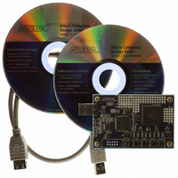
KIT MAX II MICRO
Manufacturer
Terasic Technologies Inc
Series
MAX® IIr
Type
FPGAr
Datasheet
1.P0305.pdf
(26 pages)
Specifications of P0305
Contents
Evaluation Board, Cable(s), Software and Documentation
For Use With/related Products
EPM2210F324
Lead Free Status / RoHS Status
Lead free / RoHS Compliant


3.2
The interface of the MAX II Micro control panel window matches the real MAX II Micro board.
Users can select the components they want to control directly. All configurable components are
marked with blue frame in the window.
The MAX II Micro Control Panel can be used to light up LEDs, detect the pressed action of
pushbutton switches and configure the I/O logic level of prototyping area on the MAX II Micro
board. The following sections describe how to perform these actions with the control panel already
open on the host computer
Typical design activities do not require the ability to set arbitrary values for simple display devices.
However, for troubleshooting purposes, setting arbitrary values enables you to verify that the
devices are operating correctly.
To light up the LEDs on the MAX II Micro board, you can turn the individual LEDs on by
clicking the LED icon on the control panel window as show in the Figure 3.4. The icon of the
chosen LED will be marked with yellow color.
U sing the Control Panel
1 4 B
Light up the LEDs
Figure 3.3. The MAX II Micro Control Panel concept.
USB
Blaster
15
Prototyping Area
IP
LEDs
USER
IP
Pushbutton
Switches
MMK User Manual
Related parts for P0305
Image
Part Number
Description
Manufacturer
Datasheet
Request
R

Part Number:
Description:
MODULE DIGITAL CAMERA 5MP (D5M)
Manufacturer:
Terasic Technologies Inc
Datasheet:

Part Number:
Description:
DE2-70 CALL FOR ACADEMIC PRICING
Manufacturer:
Terasic Technologies Inc
Datasheet:

Part Number:
Description:
USB BLASTER CABLE
Manufacturer:
Terasic Technologies Inc
Datasheet:

Part Number:
Description:
BOARD ADAPTER HSMC TO GPIO
Manufacturer:
Terasic Technologies Inc
Datasheet:

Part Number:
Description:
BOARD ADAPTER THDB-SUM
Manufacturer:
Terasic Technologies Inc
Datasheet:

Part Number:
Description:
KIT DEV 4.3" LCD TOUCH PANEL
Manufacturer:
Terasic Technologies Inc
Datasheet:

Part Number:
Description:
DAUGHTER BOARD AD/DA GPIO ADA
Manufacturer:
Terasic Technologies Inc

Part Number:
Description:
DAUGHTER BOARD AD/DA HSMC ADA
Manufacturer:
Terasic Technologies Inc

Part Number:
Description:
BOARD DEV/EDUCATION ALTERA DE0
Manufacturer:
Terasic Technologies Inc
Datasheet:

Part Number:
Description:
BOARD DEV DE1 ALTERA
Manufacturer:
Terasic Technologies Inc
Datasheet:

Part Number:
Description:
DE2 CALL FOR ACADEMIC PRICING
Manufacturer:
Terasic Technologies Inc

Part Number:
Description:
MODULE DIGITAL CAMERA 1.3MP
Manufacturer:
Terasic Technologies Inc
Datasheet:

Part Number:
Description:
SENSOR CMOS 1.3MEGA (FOR P0349)
Manufacturer:
Terasic Technologies Inc
Datasheet:
Part Number:
Description:
MODULE DIGITAL CAMERA 5MP (D5M)
Manufacturer:
Terasic Technologies Inc
Datasheet: