P0305 Terasic Technologies Inc, P0305 Datasheet - Page 24
P0305
Manufacturer Part Number
P0305
Description
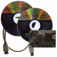
KIT MAX II MICRO
Manufacturer
Terasic Technologies Inc
Series
MAX® IIr
Type
FPGAr
Datasheet
1.P0305.pdf
(26 pages)
Specifications of P0305
Contents
Evaluation Board, Cable(s), Software and Documentation
For Use With/related Products
EPM2210F324
Lead Free Status / RoHS Status
Lead free / RoHS Compliant


3.
4.
5.
6.
7.
8.
4.5
Users can follow the instructions below to implement a color pattern generator using a 3.6’’ LCD
module with the MAX II Micro board. We are using a Terasic 3.6’’ LCD module for this
demonstration.
To connect the 3.6” LCD module to the MAX II Micro board, you need to solder a DIP 40-pin male
connector onto PROT_A (refer to Figure 4.4).
1.
Open Quartus II and locate DEN_LTM_TEST.pof under the directory \ DEN_demonstrations \
DEN_LTM_TEST \ of the CD-ROM included.
Download the bitstream (DEN_LTM_TEST.pof) to the MAX II Micro board.
Once the download is finished, Plug out the USB cable from the MAX II Micro board and
re-plug it in to power up and reset the MAX II CPLD device.
Press BUTTON1 on the MMK board to reset the circuit.
You can touch the LTM screen to switch to the other pattern.
The following table summarizes the pattern types of this exercise.
Ensure the connection is made correctly, as shown in Figure 4.7.
E xercise 3: A Color Pattern Generator Using 3.6’’ LCD module
1 9 B
Figure 4.6. The connection setup for the 40-pin cable with MAX II Micro board.
Gray bar.
Color bar.
50% gray level pattern.
White pattern.
Pattern
22
MMK User Manual
Related parts for P0305
Image
Part Number
Description
Manufacturer
Datasheet
Request
R

Part Number:
Description:
MODULE DIGITAL CAMERA 5MP (D5M)
Manufacturer:
Terasic Technologies Inc
Datasheet:

Part Number:
Description:
DE2-70 CALL FOR ACADEMIC PRICING
Manufacturer:
Terasic Technologies Inc
Datasheet:

Part Number:
Description:
USB BLASTER CABLE
Manufacturer:
Terasic Technologies Inc
Datasheet:

Part Number:
Description:
BOARD ADAPTER HSMC TO GPIO
Manufacturer:
Terasic Technologies Inc
Datasheet:

Part Number:
Description:
BOARD ADAPTER THDB-SUM
Manufacturer:
Terasic Technologies Inc
Datasheet:

Part Number:
Description:
KIT DEV 4.3" LCD TOUCH PANEL
Manufacturer:
Terasic Technologies Inc
Datasheet:

Part Number:
Description:
DAUGHTER BOARD AD/DA GPIO ADA
Manufacturer:
Terasic Technologies Inc

Part Number:
Description:
DAUGHTER BOARD AD/DA HSMC ADA
Manufacturer:
Terasic Technologies Inc

Part Number:
Description:
BOARD DEV/EDUCATION ALTERA DE0
Manufacturer:
Terasic Technologies Inc
Datasheet:

Part Number:
Description:
BOARD DEV DE1 ALTERA
Manufacturer:
Terasic Technologies Inc
Datasheet:

Part Number:
Description:
DE2 CALL FOR ACADEMIC PRICING
Manufacturer:
Terasic Technologies Inc

Part Number:
Description:
MODULE DIGITAL CAMERA 1.3MP
Manufacturer:
Terasic Technologies Inc
Datasheet:

Part Number:
Description:
SENSOR CMOS 1.3MEGA (FOR P0349)
Manufacturer:
Terasic Technologies Inc
Datasheet:
Part Number:
Description:
MODULE DIGITAL CAMERA 5MP (D5M)
Manufacturer:
Terasic Technologies Inc
Datasheet: