P0305 Terasic Technologies Inc, P0305 Datasheet - Page 7
P0305
Manufacturer Part Number
P0305
Description
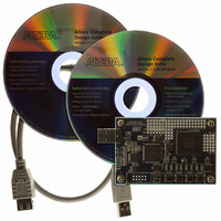
KIT MAX II MICRO
Manufacturer
Terasic Technologies Inc
Series
MAX® IIr
Type
FPGAr
Datasheet
1.P0305.pdf
(26 pages)
Specifications of P0305
Contents
Evaluation Board, Cable(s), Software and Documentation
For Use With/related Products
EPM2210F324
Lead Free Status / RoHS Status
Lead free / RoHS Compliant


2.2
Figure 2.2 gives the block diagram of the MAX II Micro board.
Following is more detailed information about the blocks in Figure 2.2:
MAX II 2210 FPGA
USB Blaster circuit
2 blue user LEDs
50-MHz oscillator for clock sources
Powered by a USB cable (Type-A-Male to Type-A-Female)
B lock Diagram of the MAX II Micro Board
4 B
2,210 LEs
272 user I/O pins
FineLine BGA 324-pin package
On-board USB Blaster for programming
Only JTAG programming mode is supported to configure MAX II Micro or when MAX II
Micro is used as a USB Blaster cable.
Figure 2.2. Block diagram of the MAX II Micro board.
50 MHz OSC
B-TYPE
USB
FT245
Button4
USB-Blaster
Button3
EPM3128
EPM2210F324
5
MAX II
Button2 Button1
JTAG
LED8…........................LED1
x88
USB Power
3.3V/1.5A
GPIO
MMK User Manual
Related parts for P0305
Image
Part Number
Description
Manufacturer
Datasheet
Request
R

Part Number:
Description:
MODULE DIGITAL CAMERA 5MP (D5M)
Manufacturer:
Terasic Technologies Inc
Datasheet:

Part Number:
Description:
DE2-70 CALL FOR ACADEMIC PRICING
Manufacturer:
Terasic Technologies Inc
Datasheet:

Part Number:
Description:
USB BLASTER CABLE
Manufacturer:
Terasic Technologies Inc
Datasheet:

Part Number:
Description:
BOARD ADAPTER HSMC TO GPIO
Manufacturer:
Terasic Technologies Inc
Datasheet:

Part Number:
Description:
BOARD ADAPTER THDB-SUM
Manufacturer:
Terasic Technologies Inc
Datasheet:

Part Number:
Description:
KIT DEV 4.3" LCD TOUCH PANEL
Manufacturer:
Terasic Technologies Inc
Datasheet:

Part Number:
Description:
DAUGHTER BOARD AD/DA GPIO ADA
Manufacturer:
Terasic Technologies Inc

Part Number:
Description:
DAUGHTER BOARD AD/DA HSMC ADA
Manufacturer:
Terasic Technologies Inc

Part Number:
Description:
BOARD DEV/EDUCATION ALTERA DE0
Manufacturer:
Terasic Technologies Inc
Datasheet:

Part Number:
Description:
BOARD DEV DE1 ALTERA
Manufacturer:
Terasic Technologies Inc
Datasheet:

Part Number:
Description:
DE2 CALL FOR ACADEMIC PRICING
Manufacturer:
Terasic Technologies Inc

Part Number:
Description:
MODULE DIGITAL CAMERA 1.3MP
Manufacturer:
Terasic Technologies Inc
Datasheet:

Part Number:
Description:
SENSOR CMOS 1.3MEGA (FOR P0349)
Manufacturer:
Terasic Technologies Inc
Datasheet:
Part Number:
Description:
MODULE DIGITAL CAMERA 5MP (D5M)
Manufacturer:
Terasic Technologies Inc
Datasheet: