C8051F320DK Silicon Laboratories Inc, C8051F320DK Datasheet - Page 149
C8051F320DK
Manufacturer Part Number
C8051F320DK
Description
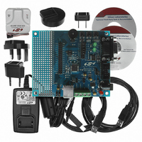
DEV KIT FOR C8051F320/F321
Manufacturer
Silicon Laboratories Inc
Type
MCUr
Specifications of C8051F320DK
Contents
Evaluation Board, Power Supply, USB Cables, Adapter and Documentation
Processor To Be Evaluated
C8051F320/F321
Interface Type
USB
Silicon Manufacturer
Silicon Labs
Core Architecture
8051
Silicon Core Number
C8051F320
Silicon Family Name
C8051F32x
Lead Free Status / RoHS Status
Contains lead / RoHS non-compliant
For Use With/related Products
Silicon Laboratories C8051F320, C8051F321
Lead Free Status / Rohs Status
Lead free / RoHS Compliant
Other names
336-1260
Available stocks
Company
Part Number
Manufacturer
Quantity
Price
Company:

Part Number:
C8051F320DK
Manufacturer:
SiliconL
Quantity:
4


15.6. Function Addressing
The FADDR register holds the current USB0 function address. Software should write the host-assigned
7-bit function address to the FADDR register when received as part of a SET_ADDRESS command. A new
address written to FADDR will not take effect (USB0 will not respond to the new address) until the end of
the current transfer (typically following the status phase of the SET_ADDRESS command transfer). The
UPDATE bit (FADDR.7) is set to ‘1’ by hardware when software writes a new address to the FADDR regis-
ter. Hardware clears the UPDATE bit when the new address takes effect as described above.
15.7. Function Configuration and Control
The USB register POWER (Figure 15.8) is used to configure and control USB0 at the device level (enable/
disable, Reset/Suspend/Resume handling, etc.).
USB Reset: The USBRST bit (POWER.3) is set to ‘1’ by hardware when Reset signaling is detected on
the bus. Upon this detection, the following occur:
Writing a ‘1’ to the USBRST bit will generate an asynchronous USB0 reset. All USB registers are reset to
their default values following this asynchronous reset.
Suspend Mode: With Suspend Detection enabled (SUSEN = ‘1’), USB0 will enter Suspend Mode when
Suspend signaling is detected on the bus. An interrupt will be generated if enabled (SUSINTE = ‘1’). The
Suspend Interrupt Service Routine (ISR) should perform application-specific configuration tasks such as
Bit7:
Bits6–0: Function Address
Update
Bit7
R
1. The USB0 Address is reset (FADDR = 0x00).
2. Endpoint FIFOs are flushed.
3. Control/status registers are reset to 0x00 (E0CSR, EINCSRL, EINCSRH, EOUTCSRL,
4. USB register INDEX is reset to 0x00.
5. All USB interrupts (excluding the Suspend interrupt) are enabled and their corresponding flags
6. A USB Reset interrupt is generated if enabled.
EOUTCSRH).
cleared.
Update: Function Address Update
Set to ‘1’ when software writes the FADDR register. USB0 clears this bit to ‘0’ when the new
address takes effect.
0: The last address written to FADDR is in effect.
1: The last address written to FADDR is not yet in effect.
Holds the 7-bit function address for USB0. This address should be written by software when
the SET_ADDRESS standard device request is received on Endpoint0. The new address
takes effect when the device request completes.
USB Register Definition 15.7. FADDR: USB0 Function Address
R/W
Bit6
R/W
Bit5
R/W
Bit4
Function Address
Rev. 1.4
R/W
Bit3
R/W
Bit2
R/W
Bit1
C8051F320/1
R/W
Bit0
USB Address:
00000000
Reset Value
0x00
149
Related parts for C8051F320DK
Image
Part Number
Description
Manufacturer
Datasheet
Request
R

Part Number:
Description:
SMD/C°/SINGLE-ENDED OUTPUT SILICON OSCILLATOR
Manufacturer:
Silicon Laboratories Inc
Part Number:
Description:
Manufacturer:
Silicon Laboratories Inc
Datasheet:
Part Number:
Description:
N/A N/A/SI4010 AES KEYFOB DEMO WITH LCD RX
Manufacturer:
Silicon Laboratories Inc
Datasheet:
Part Number:
Description:
N/A N/A/SI4010 SIMPLIFIED KEY FOB DEMO WITH LED RX
Manufacturer:
Silicon Laboratories Inc
Datasheet:
Part Number:
Description:
N/A/-40 TO 85 OC/EZLINK MODULE; F930/4432 HIGH BAND (REV E/B1)
Manufacturer:
Silicon Laboratories Inc
Part Number:
Description:
EZLink Module; F930/4432 Low Band (rev e/B1)
Manufacturer:
Silicon Laboratories Inc
Part Number:
Description:
I°/4460 10 DBM RADIO TEST CARD 434 MHZ
Manufacturer:
Silicon Laboratories Inc
Part Number:
Description:
I°/4461 14 DBM RADIO TEST CARD 868 MHZ
Manufacturer:
Silicon Laboratories Inc
Part Number:
Description:
I°/4463 20 DBM RFSWITCH RADIO TEST CARD 460 MHZ
Manufacturer:
Silicon Laboratories Inc
Part Number:
Description:
I°/4463 20 DBM RADIO TEST CARD 868 MHZ
Manufacturer:
Silicon Laboratories Inc
Part Number:
Description:
I°/4463 27 DBM RADIO TEST CARD 868 MHZ
Manufacturer:
Silicon Laboratories Inc
Part Number:
Description:
I°/4463 SKYWORKS 30 DBM RADIO TEST CARD 915 MHZ
Manufacturer:
Silicon Laboratories Inc
Part Number:
Description:
N/A N/A/-40 TO 85 OC/4463 RFMD 30 DBM RADIO TEST CARD 915 MHZ
Manufacturer:
Silicon Laboratories Inc
Part Number:
Description:
I°/4463 20 DBM RADIO TEST CARD 169 MHZ
Manufacturer:
Silicon Laboratories Inc