XE8000EV101 Semtech, XE8000EV101 Datasheet - Page 126
XE8000EV101
Manufacturer Part Number
XE8000EV101
Description
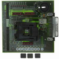
EVAL BOARD FOR XE8801AMI027LF
Manufacturer
Semtech
Type
MCUr
Specifications of XE8000EV101
Contents
Fully Assembled Evaluation Board
For Use With/related Products
XE88LC01AMI027
Lead Free Status / RoHS Status
Contains lead / RoHS non-compliant


The counters can generate PWM signals (Pulse Width Modulation) on the Port B outputs PB(0) and PB(1).
The PWM mode is selected by setting CntPWM1 and CntPWM0 in the RegCntConfig1 register. See Table 18-11
and Table 18-12 for an exact description of how the setting of CntPWM1 and CntPWM0 affects the operating
mode of the counters A, B, C and D according to the other configuration settings.
When CntPWM0 is enabled, the PWMA or PWMAB output value overrides the value set in bit 0 of RegPBOut in
the Port B peripheral. When CntPWM1 is enabled, the PWMC or PWMCD output value overrides the value set in
bit 1 of RegPBOut. The corresponding ports (0 and/or 1) of Port B must be set in digital mode and as output and
either open drain or not and pull up or not through a proper setting of the control registers of the Port B.
Counters in PWM mode always count down, the CntXDownUp bit setting must be reset. No interrupts and events
are generated by the counters which are in PWM mode. Counters do count circularly: they restart at the maximal
value (either 0xFF when not cascaded or 0xFFFF when cascaded) when respectively an underflow condition
occurs in the counting.
The internal PWM signals are low as long as the counter contents are higher than the PWM code values written in
the RegCntX registers. They are high when the counter contents are smaller or equal to these PWM code values.
The PWM resolution is always 8 bits when the counters used for the PWM signal generation are not cascaded.
PWM0Size(1:0) and PWM1Size(1:0) in the RegCntConfig2 register are used to set the PWM resolution for the
© Semtech 2005
18.10 PWM mode
dow n counting
up counting
clock counter X
clock counter X
write RegCntX
write RegCntX
CntXDownUp
CntXDownUp
CntXEnable
CntXEnable
RegCntX_w
RegCntX_w
RegCntX_r
RegcntX_r
IrqX
IrqX
XX
XX
XX
XX
Figure 18-2. Up and down count interrupt generation.
0
3
3
1
2
3
2
1
3
0
18-8
0
3
1
2
2
1
3
0
0
3
XE8801A – SX8801R
1
2
2
1
www.semtech.com
3
0
Related parts for XE8000EV101
Image
Part Number
Description
Manufacturer
Datasheet
Request
R

Part Number:
Description:
EVALUATION BOARD
Manufacturer:
Semtech
Datasheet:
Part Number:
Description:
EVALUATION BOARD
Manufacturer:
Semtech
Datasheet:
Part Number:
Description:
VOLTAGE SUPPRESSOR, TRANSIENT SEMTECH
Manufacturer:
Semtech
Datasheet:

Part Number:
Description:
HIGH VOLTAGE CAPACITORS MONOLITHIC CERAMIC TYPE
Manufacturer:
Semtech Corporation
Datasheet:
Part Number:
Description:
EZ1084CM5.0 AMP POSITIVE VOLTAGE REGULATOR
Manufacturer:
Semtech Corporation
Datasheet:
Part Number:
Description:
3.0 AMP LOW DROPOUT POSITIVE VOLTAGE REGULATORS
Manufacturer:
Semtech Corporation
Datasheet:
Part Number:
Description:
Manufacturer:
Semtech Corporation
Datasheet:
Part Number:
Description:
RailClamp Low Capacitance TVS Diode Array
Manufacturer:
Semtech Corporation
Datasheet:
Part Number:
Description:
Manufacturer:
Semtech Corporation
Datasheet:
Part Number:
Description:
Manufacturer:
Semtech Corporation
Datasheet:
Part Number:
Description:
Manufacturer:
Semtech Corporation
Datasheet:
Part Number:
Description:
Manufacturer:
Semtech Corporation
Datasheet: