XE8000EV101 Semtech, XE8000EV101 Datasheet - Page 91
XE8000EV101
Manufacturer Part Number
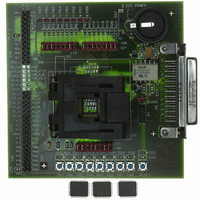
XE8000EV101
Description
EVAL BOARD FOR XE8801AMI027LF
Manufacturer
Semtech
Type
MCUr
Specifications of XE8000EV101
Contents
Fully Assembled Evaluation Board
For Use With/related Products
XE88LC01AMI027
Lead Free Status / RoHS Status
Contains lead / RoHS non-compliant


16.4.2
Figure 16-2 shows a detailed functional diagram of the ZoomingADC™. In
Table 16-10 the configuration of the peripheral registers is detailed. The system has a bank of eight 8-bit registers:
six registers are used to configure the acquisition chain (RegAcCfg0 to 5), and two registers are used to store the
output code of the analog-to-digital conversion (RegAcOutMsb & Lsb). The register coding of the ADC parameters
and performance characteristics are detailed in Section 16.7.
With:
•
•
•
•
•
•
•
•
•
•
© Semtech 2005
OUT: (r) digital output code of the analog-to-digital converter. (MSB = OUT[15])
START: (w) setting this bit triggers a single conversion (after the current one is finished). This bit always reads
back 0.
SET_NELC: (rw) sets the number of elementary conversions to 2
input signal is chopped between elementary conversions (1,2,4,8).
SET_OSR: (rw) sets the over-sampling rate (OSR) of an elementary conversion to 2
32, ..., 512, 1024.
CONT: (rw) setting this bit starts a conversion. A new conversion will automatically begin as long as the bit
remains at 1.
TEST: bit only used for test purposes. In normal mode, this bit is forced to 0 and cannot be overwritten.
IB_AMP_ADC: (rw) sets the bias current in the ADC to 0.25*(1+ IB_AMP_ADC[1:0]) of the normal operation
current (25, 50, 75 or 100% of nominal current). To be used for low-power, low-speed operation.
IB_AMP_PGA: (rw) sets the bias current in the PGAs to 0.25*(1+IB_AMP_PGA[1:0]) of the normal operation
current (25, 50, 75 or 100% of nominal current). To be used for low-power, low-speed operation.
ENABLE: (rw) enables the ADC modulator (bit 0) and the different stages of the PGAs (PGAi by bit i=1,2,3). PGA stages that
are disabled are bypassed.
FIN: (rw) These bits set the sampling frequency of the acquisition chain. Expressed as a fraction of the oscillator frequency,
the sampling frequency is given as: 00
RegAcOutMsb
RegAcOutLsb
RegAcCfg0
RegAcCfg1
RegAcCfg2
RegAcCfg3
RegAcCfg4
RegAcCfg5
Register
Default
values:
Default
values:
Default
values:
Default
values:
Default
values:
Default
values:
Name
Peripheral Registers
Table 16-10. Peripheral registers to configure the acquisition chain (AC)
BUSY
STAR
IB_AMP_ADC[
PGA1
_G
7
T
0
0
0
0
FIN[1:0]
and to store the analog-to-digital conversion (ADC) result
1:0]
11
00
SET_NELC[1:0]
DEF
0
6
01
1/4 f
PGA2_GAIN[1:0]
IB_AMP_PGA[1:
5
RC
, 01
11
00
0]
1/8 f
Bit Position
4
PGA3_OFFSET[6:0]
OUT[15:8]
16-6
OUT[7:0]
PGA3_GAIN[6:0]
RC
SET_OSR[2:0]
AMUX[4:0]
, 10
0000000
0000000
00000
010
3
1/32 f
PGA2_OFFSET[3:0]
RC
SET_NELC[1:0]
, 11
ENABLE[3:0]
2
0001
0000
~8kHz.
CONT
. To compensate for offsets, the
XE8801A – SX8801R
1
0
(3+SET_OSR[2:0])
VMUX
TEST
0
0
0
www.semtech.com
. OSR = 8, 16,
Related parts for XE8000EV101
Image
Part Number
Description
Manufacturer
Datasheet
Request
R

Part Number:
Description:
EVALUATION BOARD
Manufacturer:
Semtech
Datasheet:
Part Number:
Description:
EVALUATION BOARD
Manufacturer:
Semtech
Datasheet:
Part Number:
Description:
VOLTAGE SUPPRESSOR, TRANSIENT SEMTECH
Manufacturer:
Semtech
Datasheet:

Part Number:
Description:
HIGH VOLTAGE CAPACITORS MONOLITHIC CERAMIC TYPE
Manufacturer:
Semtech Corporation
Datasheet:
Part Number:
Description:
EZ1084CM5.0 AMP POSITIVE VOLTAGE REGULATOR
Manufacturer:
Semtech Corporation
Datasheet:
Part Number:
Description:
3.0 AMP LOW DROPOUT POSITIVE VOLTAGE REGULATORS
Manufacturer:
Semtech Corporation
Datasheet:
Part Number:
Description:
Manufacturer:
Semtech Corporation
Datasheet:
Part Number:
Description:
RailClamp Low Capacitance TVS Diode Array
Manufacturer:
Semtech Corporation
Datasheet:
Part Number:
Description:
Manufacturer:
Semtech Corporation
Datasheet:
Part Number:
Description:
Manufacturer:
Semtech Corporation
Datasheet:
Part Number:
Description:
Manufacturer:
Semtech Corporation
Datasheet:
Part Number:
Description:
Manufacturer:
Semtech Corporation
Datasheet: